Clock sculpture
Project – | Article by Maarten Tromp | Published , updated | 3090 words
Introduction
One day I wondered if it would be possible to make a wall clock out of two concentric rings with leds and all electronics suspended between them. Well, now I know. For this clock there's no need for a circuit board, in fact, it looks even cooler without. Especially with blinkenleds. This article is about my first circuit sculpture.
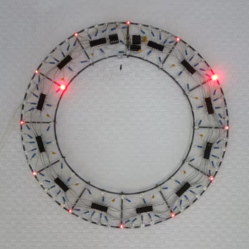 Clock circuit sculpture
This article featured on Hackaday and Hackster.io
In this article:
After working on the wedding gift for Jeroen and Mingming, I thought a lot about making cool looking electronics. So I got this idea for a clock, drew a rough sketch, and then forgot about it.
Some years later I found that sketch again and decided to see if I could actually build it. This time I made a more detailled sketch and used a handful of parts to see which size would work best for the clock. The result is 240 mm (9.5 in) diameter for the outer ring, and 160 mm (6.3 in) for the inner ring. It won't be a very big clock, but if the rings were any wider, the electronics would look very small in comparison.
Once again, form from function. You start with a circle of leds for the minutes and a smaller one for the hours, add metal rings for support, suspend the electronics in the space between the rings. That is all you need. I like that the centre of the clock remains clear, just like the sides of the bookcase for ring binders. Everything you need is contained within the ring itself. The clock looks a bit like a necklace.
The frame is made from 2 mm (0.08 in) steel wire. The wire I had was all twisted up, so I cut two pieces and straightened them by twisting between the bench vise and a cordless drill. To make the ring shapes I bent the pieces of straightened wire around saucepans. It was difficult to make the ends meet for soldering, so I routed a jig to keep everything in place with some screws and washers, so I could solder in peace.
Soldering galvanised wire with solder meant for electronics didn't work very well. It took a lot of time, heat and solder to make things stick at all and the result was a poor joint. Trying some s39 flux meant for soldering copper water pipes turned out to be a huge improvement. Now everything stuck perfectly at the slightest touch of a soldering iron, with only a fraction of the solder I had to use before.
The spokes between the rings were not in the original design, but without them there was nothing keeping both rings together. The spokes resemble hour indicators, which might make the clock more readable. First I tried to solder spokes between the rings but it turned out to be a lot easier to solder them on top of the rings instead. This also added a bit of depth to the sculpture.
If I were to build another frame, I would hard solder or weld the frame. This would be sturdier and won't come apart later on when soldering electronics to the frame.
The electronics are chosen for both functionality and looks, as they will be responsible for telling time as well as the look and feel of the sculpture. For this design I prefer the old-and-a-bit-crusty look over futuristic-and-clean. So no Neopixels, esp32 or SMD parts this time, but conventional, old-school, through-hole components. It should look like something made in the 1970s.
While the design process is described here in discrete steps, in reality many steps are intertwined. Most choices are made by roughly working out the implication of both versions and then choosing which design fits best.
Microcontroller, logic ICs or discrete DTL
The thought of building everything out of discrete diode-transistor-logic had crossed my mind, but that would be quite a bit more complicated than I wanted this project to be. Let's use integrated circuits where possible.
Making a clock entirely from 7400-series logic ICs is absolutely possible. There are many clock out on the internet (and in peoples homes) that do exactly this. But at this point the requirements for this clock are not exactly clear yet, so some experimenting is in order. And every change would mean rewiring the logic, or even adding or removing ICs.
Using a microcontroller offers by far the most flexibility, but it does feels like cheating in a mock-1970s design. On the other hand, the possibilities are enormous. There could be an hour chime en it would even be possible to PWM the leds. And development cycles would be a lot quicker than any of the alternatives. Maybe having a microcontroller would not even be all that noticeable when it's in a through-hole package, all in all it's just another DIP on the wall.
To stick with the low(ish)-tech theme, I went looking for a minimalistic microcontroller. Since I have worked with AVRs before an ATtiny seemed a logical choice. The smallest AVR that fitted the bill, both in terms of physical size and specification, is the ATtiny13a. It has 1k flash, 64 bytes ram, a 9.6 MHz internal oscillator and comes in DIP8.
All the leds need to be driven, and for that you need a lot of pins, so some form of I/O expanders and led drivers is needed. With the physical division of the clock into 5 minute sections by the spokes, it makes sense to have one driver per 5 minute section. This would keeps led wiring within a single section, and thus help to visually emphasize the 5 minute sections.
It turned out to be possible to drive the leds directly from the shift registers. The SN74HC595N can source up to 35 mA per output with a maximum of 70 mA in total. To have the option to have all leds on at the same time, that leaves 10 mA per output. This should be more than enough to drive high-efficiency leds to a reasonable brightness. The leds are connected with 330 Ω resistors, limiting output current to 10 mA.
The shift registers are physically held in place by the ground connection to the frame, resistors to the leds and the 100 nF decoupling cap.
The clock uses 84 leds in total; one per minute and one per half hour. I prefer clear leds, those provide great contrast between off and on, and, as a bonus, you can see what's inside. They're not quite as old school as the red cases, but I choose those anyway. These specific leds have a very wide opening angle, so the clock will be visible from almost any angle and, because of the high efficiency, use little power.
Originally I wanted 5 mm leds for the clock, so that's what I had ordered. When I received the leds I installed them on the frame. It wasn't until a few months later, when I saw the original order again, that I realized I had received 3 mm leds instead.
Because of the power draw, the clock is mains powered. The transformer was left over from the digital chandelier I had built and dismantled before. It's a tiny 9 V transformer with only a few VA, but it's still too big to fit within the frame. So instead it's implemented as "line lump". From there a wire runs to the frame where the rest of the power supply is located. The voltage is a bit on the high side for a 5 V power supply but this was the most compact transformer I had.
Regulation is done with minimal parts. One side of the transformer secondary is connected directly to the frame, which is the system ground. Rectification is done with a single diode and capacitor, followed by a 7805 voltage regulator. It's not the most efficient of designs, but current is quite low, so power loss is not too bad.
Typical current draw of the clock is 20 mA. Maximum current (all leds on) is around 500 mA, which is more than the little transformer can deliver, but only a few leds should be on at any given time anyway.
For keeping proper time, you need a stable clock source. Luckily, with the clock being AC powered (not really a coincidence), we the the have mains frequency available. In the Netherlands (where I live) mains frequency is kept stable enough to be used as time base by clocks (called synchronous clocks). While the mains frequency can vary slightly over the course of a day, this is compensated for once per day, so the exact number of cycles is always run in a day.
To obtain mains frequency, unregulated power (directly from transformer secondary) is also connected to the AVR. A series resistor and the AVR internal protection diodes take care of the over/under voltage by clamping it to the power rails. According to AVR application note 182, you can even do this directly on mains Voltage, without a transformer.
Everything is connected with wires from an old ribbon cable (an IDE cable actually, that's what harddisks were connected with before there was SATA). I learned this trick from Sprite_tm around the turn of the century and have been using it ever since. But be careful though when soldering pins that are close to a wire, because the isolation can melt causing hard-to-find shorts.
Before anything behaved properly, I had to spend a fair amount of time debugging the system.
First of all, in system programming (ISP) of the AVR did not work. I had to pull the microcontroller from its socket and plug it into the programmer for every development cycle. Eager to get the firmware development going I accepted this quirk and started writing some code.
But whatever code I wrote, the AVR behaved randomly. Outputs were switching erratically and none of the changes I made in code changed that. After comparing with a known-good project I found that in the clock Makefile the C source code was compiled to ELF, which was flashed by avrdude. While this should work in theory, in practice it didn't. When I changed the Makefile to compile to BIN, then use avr-objcopy to convert BIN to IHEX and flash that with avrdude, it worked as intended. I'm not sure exactly why it didn't work before, but at least I could now properly program the AVR.
With programming working, I noticed that one of the AVR output pins was always high, no matter what I did in code. After lots of increasingly trivial tests I realized there must be a short to VCC. Earlier I had checked all wiring for continuity and shorts to ground, but forgot to check for shorts to VCC. Many wires run close together between the shift registers and at some point one must have shorted to VCC when a nearby pin was soldered. With the short removed I gained full control over the AVR output pin. From that moment on ISP also worked.
Now that everything behaved properly I could finally start on the actual firmware development.
The firmware is written in C instead of assembler for a change. The AVR doesn't have any division or multiplication instructions, but avr-gcc can emulate those if needed. I expected to use division and remainder quite a bit, so I choose C, but ended up using not using any at all.
Since the ATtiny13a does not have a shift register driver onboard (such as SPI), the shift register output is bit-banged. This can be done in a few lines of code and works just fine. To get a higher data rate I could maybe have used the UART, but for now I didn't need the extra speed.
The shift register data is re-calculated from hour and minute values every time the display changes.
The display update speed is high enough to be useable for PWM. To create a nice looking fade-in and fade-out I made a logarithmic lookup-table (which is a lot faster than calculating it, like in the wake-up-bright). With some code optimizations and the right compiler settings I managed to squeeze out 8 bit software PWM at a 50 Hz refresh-rate.
One of the ideas was to make the clock brightness respond to ambient light level. The PWM routine was quite busy with fading leds in and out without adding additional brightness values to it. Besides, the contrast of 8 bit PWM was already quite poor and lowering maximum brightness would only make it worse. Luckily there's an additional way of dimming the entire display, with minimal overhead.
The hardware PWM output of the AVR is connected to the output enable (/OE) of the shift registers. By varying the hardware PWM duty cycle you vary the time the display is actually on, extending the range of the software PWM. An unexpected side effect was that the display started to visibly flicker. I hadn't thought about it, but you are mixing frequencies (of hardware PWM and software PWM) and you can see some of the resulting frequencies in the form of a tremolo effect. This flickering made the display unusable, so I gave up on this experiment and removed the additional PWM hardware and code from the clock. When the fading-effect was no longer used I also removed the software PWM from code.
Dimming the 5 minute markers
With all forms of brightness control stripped from the clock, the 5 minute markers still had to be dimmed. So we're going back to a minimal sort of PWM. After the mains zero-crossing interrupt fires the markers are displayed, and immediately the "hands" are shown again. This short blink of the markers creates a nice dim glow. With a 50 Hz refresh-rate there is no visible flickering. The refresh-rate could be made higher, but then the markers would become brighter as well. As a bit of over-optimization I made 2 different versions of the display routine, one for markers and one for the "hands". This makes switching between those even faster as shift register data doesn't have to be recalculated multiple times per PWM cycle. The duty-cycle looks around 1% and is just right for a nice glow.
Mains frequency is wired to the INT0 input of the AVR and a rising-edge interrupt is configured. Any other input pin could fire a pin change interrupt, but only INT0 had edge select. During every interrupt a mains-cycle counter is increased and when the counter hits 50, exactly one second has passed.
It would be possible for mains spikes and noise to also trigger the interrupt and throw off time-keeping (like it did with the chandelier dimmer), but in practise the clock runs perfectly stable. I was afraid that the interrupt routine would cause a visible flickering of the software PWM, but that also turned out not to be a problem.
The clock can be somewhat difficult to read, mostly so when the "hands" are close together. My guess is that we unconsciously use the origin of the hands as reference, but the centre of this clock is empty. Most other ring clocks I've seen have something in the centre of the ring, such as a digital readout, which seems tot help. However, you get used to reading this clock after a while.
With enough ambient light you use the 12 frame spokes as 5 minute reference. That is why I have chosen to support the frame this way. But without ambient light you can't see the spokes and telling time becomes more difficult. I have experimented with dim leds as quarter markers and as 5 minute markers, on the inner ring, the outer ring and both at the same time. What seems to work best is 5 minute markers on the outer ring, it "feels" the same as the spokes. Those might be beneficial to daytime reading as well, and make the clock look more "alive". At night the combination of glowing markers and industrial look of the frame remind me of the lights on transmission towers.
Instead of leds being fully on or off, I wanted to try fading between adjacent leds. Over the course of a minute (or an hour for the inner ring) one led would slowly grow dimmer while the other grows brighter. This should give the feeling that the "hand" was in between the two leds. Unfortunately the effect wasn't nearly as good as I imagined. Brightness differences are remarkably difficult to spot for all but the extreme cases, and the combination of 2 fading hour leds, 2 fading minute leds and all of the 5 minute markers made the clock look chaotic and more difficult to read, rather than more precise. Although I like the fading idea, being able to tell time has priority for me.
One thing that really improved readability was adding half-hour leds. Around the half-hour mark it was guesswork if it was half past the shown hour or half to. The half-our leds now make it perfectly clear. The quarters don't pose any difficulty, so there is no need to install even more additional leds on the inner ring.
Features that didn't make it
Several features never made it into the clock. For instance, I had forgotten all about the piezo speaker and hour chime until I was writing this article and found it in some old notes. Luckily my server already plays hours chimes.
Since the responding to ambient light level idea was abandoned, the LDR was never installed.
One last thing that's missing are the buttons for setting time. I was so eager to get on with the rest of the clock that I kept postponing it, thinking I didn't need the buttons right now, I'll just add them later, until there was not space left on the frame where they could reasonably go. The only way to set time now is to power on the clock exactly at high noon or midnight.
The clock in this article is developed using free and open source software and hardware where possible. Firmware is written with Vim, compiled with GNU Make and avr-gcc and programmed with AVRDUDE and USBasp.
In turn this design and article are released into the public domain. You can find all relevant files in the downloads directory of this article.
Had I known all of this before, I could probably have made the clock with just shifters and counters instead of a microcontroller. But with all the experimenting I did, I'm glad I choose a flexible design, even if it's a bit of an anachronism.
The clock has been on my wall ever since it was (mostly) finished. Setting time is a bit tricky, but I love the looks of the clock and the glow when it's dark.