Digitally enhanced chandelier
Project | Article by Maarten Tromp | Published , updated | 2171 words.
Introduction
This article describes my quest for the perfect dimmer for my chandelier. Over the years I worked on several modifications to gain remote controlled brightness per lightbulb, and then successively undid all the changes to arrive at a dimmable chandelier once more.
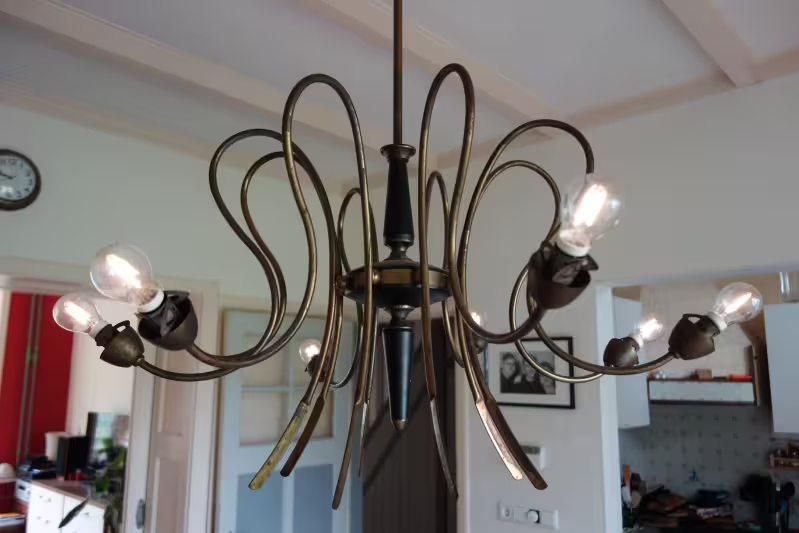 Chandelier hanging in the living room
In this article:
In 2004 I moved into one room of an 1920s directors house. It had big rooms, high ceilings, leaded windows and a wooden floor. It was huge, especially in comparison with my old student room. So I was looking for a way to emphasize its huge-ness and a big chandelier would be perfect. With my birthday coming up, I asked for a chandelier and that was exactly what I got. My dad had found one in a second hand store, it was an old, curly, brass monster, in other words; it was perfect.
It turned out the wiring was as ancient as the chandelier itself. In the old days they used linnen cloth (mixed with asbestos) as insulation. There also was no mains earth connection, there never are on old appliances. I didn't dare connect it to mains like that.
While looking for replacement wiring I found out that the arms of the chandelier were too narrow for normal wiring. The best I could find was 0.35 mm² (22 AWG) loudspeaker wire. This type should not be used for mains wiring as it's only rated for low voltage, but there was nothing else that fitted through the arms.
Also I wanted to add a mains earth connection. The entire chandelier is conductive after all. But, once again, the narrow tubing would not accommodate the extra wire. With a bit of "shopping" around the house, I liberated the smallest diameter 3 conductor double insulated cable I could find and it just fitted in the tubing. It took quite a it of additional drilling, filing and sanding to get it out of the hole in the side of the main tube. But now at least the chandelier is properly grounded and has a proper lead.
With the new wiring in place, I screwed in some bulbs and powered it up. The chandelier lit up brilliantly, but it turns out that 8*40 W bulbs create a huge amount of light. My room looked more like an office with fluorescent lighting, rather than the candle like lighting I had hoped for. Even when I replaced the bulbs with the lowest power ones I could find (15 W), it was still way too bright.
So it looked like I would need a dimmer to bring brightness down. Since I didn't have one and there's no fun in buying one, I went for the obvious solution and decided to make one myself.
In the mean time I still needed a way to bring brightness down, so I wired the bulbs per 2 in series. When you compare power dissipated in 2 identical resistors in series with that of the same 2 resistors in parallel, total output power in series configuration will be a quarter of the parallel configuration. With lightbulbs light output will be even lower than a quarter since bulbs output very little light at low voltages. So now the chandelier was too dim to be usable, even with the 40 W bulbs installed. Turns out that was a dim idea. But it's time to leave the chandelier alone and get started on making a dimmer.
A commonly used way to dim mains bulbs is phase cutting. This is like pulse with modulation on the mains frequency. You limit power to the bulb by limiting the time the bulb is exposed to mains voltage. Usually a triac is used to switch mains. Once switched on, the triac conducts as long as there is a current through it. With a resistive load (like a lightbulb), the current drops to 0 when the voltage drops to 0, and this happens at every zero crossing of the mains voltage, so 100 times per second for 50 Hz mains.
With the end of the pulse fixed on the zero crossing, the start of the pulse will have to be varied with the dimmer setting. The earlier the pulse starts, the higher the duty cycle, the more power is transferred to the lightbulb, the brighter it lights up. Power transferred is not exactly linear with the pulse-width, because the power is not evenly distributed over the time, but sine-shaped, and bulb brightness is voltage dependant. However, this can all be compensated for in dimmer firmware.
How should this new dimmer be controlled? The coolest and most futuristic thing I could imagine (back in 2006) was to have it computer controlled. It would be a lovely combination of old and new tech, and bring the chandelier into the new millennium. With computer control the chandelier could even wake me up in the morning with my own personal sunrise. (Like the wake up bright I made some years later.)
I didn't know much about USB and it seemed difficult to implement. Ethernet would be even more complex. So I went with a good old serial connection, which is easy to implement on both sides.
Now that the dimmer will be computer controlled, I didn't need the light switch any more. So it made sense to have the dimmer inside the chandelier instead of in the wall switch cavity. There should also be a bit more room inside the chandelier. Additional advantage is that the digitally enhanced chandelier will be entirely self-contained.
When I explained the chandelier dimmer plan to my friend Tom, he naturally assumed that it would be dimmable per light bulb. That wasn't part of the specification yet, but I didn't see why not, so I added it to the requirements. It would not be more difficult than making a single channel dimmer, just duplicate the output bit times the number of bulbs.
Obviously I needed galvanic isolation. The dimmer will be connected to mains voltage and to my computer at the same time (via the serial port). From previous mains switching and dimming projects I new triacs don't offer any galvanic isolation, so it has to be explicitly added.
The hub of the chandelier was mostly filled with wiring. There was some space left for a dimmer, but it had to be compact.
The microcontroller that runs the show is an Atmel AT90S2313. I had bought those in bulk for another project (phone cost registration system), a few years earlier and use them everywhere. It will deal with measuring zero crossings, phase cutting and handling the connection with the computer. It runs at 1.8432 MHz to get the timing right for the UART.
In some old electronics magazine I read about connecting a led directly to mains with only a capacitor in series. The led would blink at the mains frequency, which is exactly what I needed. To get galvanic isolation one end of a TIL111 optocoupler is wired in series with the led, with the other end connected to the AVR.
The bulbs will be switched by triacs, which can handle mains voltages and bulb current, but do not offer any galvanic isolation. Those will be driven by optotriacs, which can't handle much current but offer galvanic isolation. I learned about this trick from the Elektor book Lighting technology for stage and disco by Michael Ebner (2003). They used the MOC3020 optotriac, therefore so did I.
Looking back I seem to have forgotten to add the triac and drove the bulb directly from the optotriac. The 174 mA (40 W / 230 V) doesn't seem to have caused any problems. I also notices a complete lack of interference suppression in my design.
The power supply is a simple linear one, as the AVR uses very little power. A compact 9 V transformer (re-used from a fader-start board from the local radio station, and later re-used in a clock) and 78L05 regulator with some caps was all that was needed.
For the serial connection I repurposed a serial cable from the microcontroller workshop I had organized. It handled all the level shifting on a tiny pcb inside the plug, so it could interface directly with the TTL signals on the AVR. It would be possible to add galvanic isolation here as well, but you would need an additional isolated power supply to drive the computer side. Since mains is already isolated I didn't add any here. The serial cable did not fit through the chandelier tubing though, since all the space was taken up by mains wiring, so I let it just hang out of the side of the hub for now.
The dimmer is built on prototyping board without copper pads. It was wrongly ordered for another project, but it saved me drilling out the pads around mains tracks.
Once the hardware was finished I could start working on the firmware. First I had to obtain the time between zero crossings. Instead of hard-coding an interval of 10 ms, the firmware measures it, allowing for mains frequency fluctuations and operation on 60 Hz systems. Ideally the measured value would be averaged to smooth out mains peaks and noise, but I never got around to actually doing that.
Next came calculating the timing for the 8 outputs. The AVR only has two timers and a single PWM channel, so the firmware creates 8 software PWM channels with a resolution of 5 bit. The time between two zero crossings is divided into 32 (5 bits) slices, and once a slice starts, if there is a channel with exactly that brightness value, the corresponding output is activated. The resolution can probably be extended another one or two bits.
For communication with the computer there's a 115k2 bps serial connection. On the computer side it runs inside a serial terminal emulator. On the AVR side a few simple commands for on/off and brighter/dimmer are implemented.
When I tested the dimmer, I noticed something odd. Starting at a brightness value of 0 the bulbs were quite bright already. Increasing brightness value made the bulbs brighter, but only up to a point when they suddenly went off. From that point on brightness would increase again nicely and stop at about the same brightness as it started at value 0. It looked like there was an offset between the brightness values and actual bulb brightness. It took me a while to figure this out, searching the firmware for errors, but it turned out to be in hardware. The phase shift between mains zero crossing and the AVR interrupt was caused by the series capacitor in the zero crossing detection circuit. While I could have changed the hardware, I just adjusted for the offset in firmware.
The dimmer had the annoying habit of flashing brightly when an inductive load was switched on (such as a vacuum cleaner). This is probably because of mains line noise and should be fixed once some filtering and averaging is in place.
Once the firmware was usable, I hung the chandelier on the ceiling and had it permanently hooked up to my computer. The room light switch was always on, so the chandelier had power, but brightness was set from the terminal. While it worked, it was a bit cumbersome to have to go into my room in the dark and unlock my computer to be able to get the lights on.
After doing this for a while I set initial brightness to 25% in firmware. Now I could use the room light switch to power cycle the chandelier and get some light, without having to use the computer.
Since I hardly used the computer for controlling the chandelier, after a while I removed the serial cable. Now I had a chandelier that you could switch on or off, not unlike the earlier version with bulbs in series. But it blinked every once in a while when there was mains line noise.
So about a year later, to get rid of the flickering and blinking, I removed the PCB and rewired the chandelier to have the bulbs in series again.
Another couple of years later I wanted to be able to dim the chandelier again. But this time I rewired all the bulbs in parallel and bought a wall dimmer. It's a bit of an anti-climax, but at least I have a working dimmable chandelier now.
Success, by some definition, isn't about the end result, it's about what you learn along the way. And this project has been a real learning experience for me. While I had written software in Basic and C, this was the first time writing microcontroller firmware and using assembler. So I sat down with the AVR datasheet and a few code examples to figure it out. This was also the first article I have written (and in English, with a dictionary in hand) and published on my website. That's a lot of firsts, but it opened up a slew of possibilities for future projects.
My friend Gert uses the story of this chandelier to describe to his non-technical friends how engineers think.
All relevant material is available at the downloads directory.