Tetris window
Project – | Article by Maarten Tromp | Published | 6754 words.
Introduction
Ever wondered what happens when an apartment window meets retro gaming? Picture this: a life-size display and your neighbours battling it out in Tetris. This article is your tour behind the screens in making that happen, from the initial spark to the final showdown. We'll dive into the nitty-gritty of hardware, software, and all the highs and lows along the way.
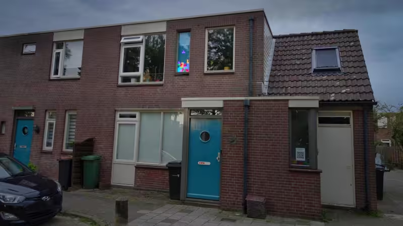 Finished Tetris window
This article featured on Hackaday.
In this article:
It was two days after moving into my new apartment, and I had just unpacked my Tetris lamp. Looking around for where to put it, I temporarily placed it on the sill of an odd tall window in the living room. The lamp is a bit of an eye-catcher and instantly recognizable with bright colourful tetrominos (Tetris blocks). Sitting on the sill, it would even be visible from the outside, spreading a bit of computer game nostalgia around the neighbourhood. For even better visibility I moved the lamp from the sill into the window frame, and it turned out they have identical depths. The window also turned out to be exactly 10 minos (blocks) wide. The tall, narrow window even looked like the Tetris playfield.
Now I obviously needed more Tetris lamps to fill the entire window. After a bit of searching, those lamps turned out to be discontinued, and used ones were scarce and priced accordingly. This would become an expensive quest, especially when you need many and have to have them shipped in from all over the world.
Just because a single part is not easily available is not a reason to give up on a good idea. Even if it's the main part or, in fact, the only part. I could make a wooden grid in the space where I would otherwise have placed the lamps. Each grid cell would hold a LED, and the grid would make up the replacement Tetris lamp display.
But with individually addressable LEDs there is no more need for a static display. The grid makes up a matrix display capable of showing live Tetris as well. With that in place, I would be able to actually play Tetris on my living room window. But not just me alone, the whole neighbourhood could join me.
Not wanting to commit to the project by immediately buying hardware, I started with the software. This is a trick I use to prevent my house from overflowing with parts I didn't need after all (and to prevent my budget from draining accordingly). Writing software only costs time and energy, but not space or money. Once I had a software proof of concept I could decide to commit on project and start shopping for hardware.
The Tetris project is made up of three pieces of software. First, there is the controller, which is what you hold in your hand to control the game. Next there is the backend, where the game logic lives. It receives user input from the controller. And lastly, there is the display driver, which controls the coloured LEDs that make up the display. It receives data from the backend.
This project offers plenty of opportunities to learn new things. Such as asynchronous real-time communication between the different pieces of software, written in different languages, and running on different platforms.
Software turned out to be the bulk of the project. I did not plan ahead a lot, just set a general direction. Start somewhere and make sure you don't program yourself into a corner.
Because you have to start somewhere, the first thing I made was a simulator of the display. It's a software version of what the hardware would be like once it's finished. The simulator is essential for bootstrapping software development. But even when the hardware is finished, it's still a handy tool to have around. It allows me to program from the comfort of my living room, without having to go outside to the display to check if my code works.
First thought for the simulator was to make a full application. But having it run in-browser makes it a lot more portable and considerably easier to write. The language of choice therefore is JavaScript. One day, I will look into TypeScript, but not today.
The simulator mainly consists of an HTML table with the same number of rows and columns as the hardware display. The script connects to the backend as if it were the hardware display and each table cell is updated as if it were a LED. It's a simple piece of code.
To start on developing the display simulator, I opened a local HTML file in the browser. It included a JavaScript file that opened a WebSocket. This seemed trivial, but LED to all sorts of weird and wonderful issues, since my browser blocked everything it considered insecure. You are not allowed, among other things, to open WebSockets unless those are over HTTPS. That seemed sensible behaviour, though somewhat inconvenient for me. So I spent some time setting up HTTPS on the receiving end, but that was still considered insecure because I had used a self-signed certificate. After grumbling a bit I decided to get this over with once and for all and set up a proper proxy server with a proper TLS certificate. This was how I wanted it to work eventually, I had just not expected it to be needed this soon.
After writing down some ramblings for this article, about the hoops one has to jump through just to be able to start development, I discovered that I had enabled HTTPS-only mode in Firefox a few months earlier. That would explain the strict behaviour. Well, at least HTTPS is properly configured now, ahead of schedule.
The controller is also made to run in the browser. This way, anyone could use it on their phone. The looks are modelled after the Nintendo Entertainment System (NES) controller, one of the iconic game controllers from the 1980s. People of a certain age will certainly recognize this. And I love the retro vibe.
For a while I had this idea about installing a physical NES controller outside my house, in front of the display. But a reality check made me realize that it would get either vandalized or perish in the rain. So the idea progressed from physical to virtual. People will be more careful with their own phone than with a public terminal. Then I wanted to setup an open WiFi accesspoint just for playing Tetris. There are some advantages to doing this, but I wanted playing Tetris to be as easily accessible as possible. And having to connect to the WiFi seemed like an unnecessary extra step. Besides I wasn't sure people would connect to unknown WiFi. Therefore the Tetris backend is now reachable over the internet and accessible from everywhere. Though the only place to be able to see the display is in front of my house.
The controller is basically an image of a NES controller with a bit of JavaScript to send button presses to the backend. You can control it with a touch screen, but I also implemented handlers for keyboard, mouse, and even gamepad. Around the button code sits a state machine that handles the backend connection and screens for entering name, player queue, game-over, etc.
I tested the controller in Firefox and Chromium, but since I didn't have a smartphone or even a device with a touch screen, I had to borrow some to do some more testing.
And when I finally had the controller working properly across all browsers and devices I could find, a neighbour let me know that it didn't work on their iPhone. Getting everything to work on Safari was yet another chapter of debugging. Even getting access to an iPhone for testing turned out to be tricky. While many people around me had Android devices I could use, none had any Apple devices.
A friend suggested this website where you had access to a bunch of connected iPhones. My free account worked fine for 25 minutes but then stopped until I would pay for a subscription. This was long enough to find out Safari 15 and older had more issues than more recent versions, and I was even able to work on a few fixes. Instead of creating more free accounts I had another idea; installing Safari on Wine. While this worked, the Safari version was way too old to be useful. More recent versions of Safari only ran on Apple hardware, which I didn't have. So I attempted to install MacOS on VirtualBox, but didn't get the installer working properly. Meanwhile I was emailing back and forth with the neighbour with the iPhone. Every time they walked their dog, they tested Tetris and emailed me what was working and what wasn't. I then searched the internet for these issues, implemented possible fixes and let the neighbour test again. (Is this what is meant by remote debugging?)
Finally I got my hands on an iPhone, thanks to another friend. It ran IOS/Safari 15, just the problematic version I was looking for. It choked on fullscreen(), vibrate(), focus(), WebM file format, etc. Luckily the issues were easy to work around, and now I could test all fixes myself.
However, I couldn't get the WebSocket to connect. And to view errors on mobile Safari, you have to connect your iPhone to a Mac, which I didn't have. After a fair bit of digging into SNI, TLSv1.2, NSUrlSession, CORS, and CSP, I found out that Content Security Policy connect-src "self" does not resolve to WebSocket schemes in all browsers. In other words, you have to explicitly add the WSS URL to connect-src to make WebSockets work on Safari. And once I had done that, the WebSocket finally connected. Again one of my security settings has backfired for development.
These issues aside, Apple's interpretation of the open standards is just as valid as the other browsers'. The browser landscape is becoming very monotonous again (just like in the 1990s with only Netscape and Internet Explorer). To keep an open standard functioning properly you need to have a few more parties involved.
The backend is the main software component. Controllers provide its input, displays accept its output, but everything in between is done by the backend. The backend is written in Python, as it has the right whipuptitude for this kind of project. It runs on a Raspberry Pi, mounted behind the display enclosure.
WebSockets is a communications layer on top of HTTP. While HTTP only allows requests from client to server, WebSockets allow both ends to send messages at will. The controllers connect to the backend over WebSockets, and so does the display. To accommodate this, the backend runs two independent WebSocket servers.
At the heart of the backend is the game manager. It's a state machine which decides what to run at any given time, and where to route controller input.
Most people associate Tetris with the Game Boy, but it originated as an early 1980s computer game.
The game looks simple, but it's full of hard-coded lists of shapes, wall-kicks, and delays. There are even more edge cases to implement.
Searching for more details, I came across the Tetris wiki which holds a wealth of information about all aspects of the game and popular implementations. This makes for great reading, but can be quite a rabbit-hole.
My friend Jeroen (also known as Sprite_tm) once implemented Tetris on an AVR in approximately 500 lines of assembler for a hardware Tetris unit. You had to plug in into a serial port and access it via a terminal emulator to play Tetris.
Before I started on Tetris, I wrote a Snake game, as it's less complex to implement. I used it mainly for testing controller input. Afterwards, I decided to keep it in, even though the project was envisioned as Tetris-only, because it's a fun game to play.
Most people know Snake from the Nokia phones, but it actually dates back to the 1970s.
Tetris, like all other games, needs a source of random numbers. In Python, these come from a pseudo-random generator. Initialized with a seed value, it outputs a stream of seemingly random numbers. Starting the generator again with the same seed value will produce the same stream of "random" numbers. And this is exactly what I needed for game replay.
At the start of each game a random seed is generated. The seed is stored, along with the controller output, so that the entire game can be replayed later. But for some reason, this didn't work quite right. Replays started the same as the original game, but deviated after a while. But not even two replays were the same. At first, I thought replay of the controller output was at fault, but digging deeper, I found each game replay received a slightly different stream of random numbers. Since all replays start with the same seed value, this should not be possible. Unless, that is, random numbers are also used somewhere else in the code. My guess was that the WebSocket module used random numbers, and disabling WebSockets indeed solved the random problem, but now the backend had no way to communicate with controllers or displays.
To make game (re)play robust against other parts of the code using random values as well, I came up with the following. Immediately before using a random value, the random generator is initialized with a new seed value. There is little chance of WebSockets stealing a value between initialization and first use. And what happens afterwards is not an issue, because the random generator is re-seeded before the next use in game (re)play. To have different seed values each time, the seed is stored and incremented by one. So a predictable stream is turned into a pseudo-random stream.
All games recorded and replayed after this change behaved as they should. In hindsight, there might be a more elegant solution than messing about with the built-in pseudo-random generator.
The actual display driver is just as simple as the display simulator was. It connects to the backend, receives display data, and outputs it, virtually unchanged, to the LED pixels.
To minimize the number of different languages and technologies in this project, the display driver is also written in Python and uses WebSockets to communicate with the backend. Opening a WebSocket is trivial, and TLS/HTTPS is handled automatically, unlike running a WebSocket server.
With every display update, the backend pushes new pixel values over the connection. All the display driver needs to do is sit and wait for updates.
On the output side of things, the software drives a string of NeoPixel LEDs using the Adafruit NeoPixel library. This, again, is made very easy. It reminds me of controlling NeoPixels on MicroPython, which I did for a wedding gift for a friend.
Running your code as root in a production environment is generally a bad idea. So I created an unprivileged user for running the backend and display driver. But without the proper permissions, it can't access GPIO pins and thus can't control the LEDs. How do we get this working?
Luckily this has already been addressed in the Adafruit CircuitPython NeoPixel howto. The trick is to use SPI0 MOSI to drive the LEDs. This output can simply be made accessible by adding the new user to groups spi and gpio. Make sure UART and SPI are be enabled in boot.txt.
Starting the software by hand is fine for testing, but how do you ensure it comes up again after a reboot? Ideally both backend and display driver should be run as a daemon.
This subject also has been addressed, countless times, by other people. What got me started was a Domotic Project blog post. And to fully understand dependencies and order, there's always the official systemd documentation. While it's entirely possible to write a daemon in Python, it's not needed in this case. Systemd just runs the Python scripts in the background, and logging is redirected from console to a file.
The enclosure for this project is a flat box that fits snugly inside the window frame. It's a sandwich of diffuser, compartment divider, PCBs, wiring, and back panel. It took a few different designs, including modular and portable versions, before I settled on this design, which is simplest of all.
For a proper Tetris playfield, the display needs to be 10 pixels wide. The window is 400 mm wide, which makes the pixels 40 mm wide. This is identical to the Tetris lamp that inspired this project.
The window is 1370 mm high. Because of the viewing angle, from street level to the upstairs window, the bottom 10 mm of the display is obscured by the window frame. Having square pixels in the remaining space would result in a display height of 34 pixels. I decided to make the pixels slightly taller, and have the display only 30 pixels high. This results in a slightly less odd aspect ratio, and due to the viewing angle, the pixels appear even more square than if they were truly square.
To divide the window into pixels, divider walls need to be placed between all rows and columns. To stop light from shining out the sides you need side walls as well. Ideally all walls should be quite thin, to not take up too much of the limited pixel surface area.
The material I picked for the walls is 3mm plywood. It's easy to work with and you can cut it into long strips without breaking. Any thinner would break, and any thicker would occupy too much of the window space. Additionally, it's the same material I intended to use for the back panel, simplifying the bill of materials.
I cut the sheet of plywood into strips with a circular saw. Next, notches had to be cut wherever a row divider intersects with a column divider. With 10 rows, 30 columns, 4 side walls, and 2 notches per crossing, that's an awful lot of notches to cut. To bring this number down I stacked a number of strips on top of each other and cut the whole stack at once with a jigsaw. While this worked, I'm frustrated with the lack of precision. All notches seem to be too shallow, too deep, too narrow, too wide, off-centre, or a combination of those. But not even two strips were the exact same width. If I were to make another compartment divider, I would opt to have all parts laser cut.
With a bit of puzzling, forcing, and widening notches, I managed to fit everything inside the window frame. Once I had established the correct order, I glued all strips in place, one at the time, inside the window frame.
For the back panel I had to decide whether I wanted the display viewable from the living room-side or not. It would be nice to be able to see what's going on, and having the ability to play Tetris from the comfort of my couch. But having an always-on blinking display prominently in my living room didn't sound very appealing. So I decided on a closed back.
Where and how exactly to place the LEDs was a bit of a puzzle. If I were to mount the LEDs inside the compartments, it would be difficult to service, and the order of installation would be tricky. So instead, I cut holes through the back panel, in the centre of each compartment, and mounted the LEDs from the back. It may not look as pretty from my living room, but it's much easier to install and service the LEDs.
The back panel is oversized, so it can be screwed onto the window frame. The compartment divider and back panel are glued together for stability and to prevent light leakage. Everything is painted white for reflection. I thought that having black edges against the diffuser might look better that white, but I never got around to comparing them. Everything warped slightly during painting, so I was glad to be able to mount it securely to the window frame.
At the start of this project, I roughly knew what a diffuser did, so how hard could it be to use one? Turns out diffusers are a discipline al by themselves. There are so many different types, all for different applications, environments, temperature ranges, etc. There are even specialized shops (of course there are). So I'm grateful for the professional help I received from kunststofshop.nl.
The diffuser for the Tetris display is a 2 mm thick sheet of white acrylic. It's cheap, easy to work with (two of my favourite properties), but also it clearly shows the pixels without smearing, and it doesn't take up too much of the limited available depth. Light transmission is a bit low at 40%, as have all white acrylic sheets, regardless of thickness. I found this out later, while wondering why the display was so dim.
The diffuser looked a bit scratched, and there was a production stamp in the middle of the panel. I accepted this as good enough. But just before installing I noticed there was a protective peel over the panel. Upon removing the peel, the diffuser looked very nice and smooth after all. So I installed it on the freshly cleaned window without touching any of the surfaces.
Before attaching the sandwich to the window frame, quite a bit of light leaked between pixels. Compressing it improved the display a lot, but there still is a bit of leaking. Maybe I should have used sealant between compartment divider and diffuser.
The moment to commit to the project had come earlier than I had anticipated. After only a few weeks of experimenting with code and toying with ideas, I was contacted by PCBWay (affiliate link). They liked my projects and offered to sponsor PCBs for my next build. I happily accepted and immediately started on a PCB design.
In the Tetris project, the electronics are actually the simplest part. There are many LEDs, each on its own identical tiny PCB, all wired into a long chain. Additionally, there's only a power supply and a Raspberry Pi, delivering power and data to the chain of LEDs.
Crucial component of the display is the LEDs. But which LEDs should I use? There are so many options to choose from. For this project I prefer NeoPixel LEDs, because you can input all RGB values, and let the NeoPixels take care of the rest. However, there are many types of NeoPixel.
RGBW looks nicer than RGB, especially in static images. Although I wasn't sure I needed this, I was like to try them. Unfortunately, the choice in RGBW is much smaller than for regular RGB, and consequently, the prices are higher. Based on the pricing, I chose RGB.
From a stability point of view, I prefer an SPI interface over the single-wire protocol, since it's less sensitive to timing. However, selection of NeoPixels with SPI interface is limited, and the prices are higher. RGBW LEDs with an SPI interface are even rarer. One advantage of the single-wire protocol is that it requires only half the wiring of SPI, so I opted for the single-wire version.
Thus, I ended up with the most common and affordable solution; the WS2812B. This is the same type of LED I had chosen for the wedding gift for my friend. Using the single-wire protocol in Python on a Raspberry Pi worked just fine; I haven't had any timing issues at all.
These LEDs are incredibly bright when you look directly at them, so I never imagined the display would be poorly visible in daylight. I forgot that the light from a single LED now has to illuminate up an entire pixel with 100 times the surface area of the LED. For a daylight-visible display, you would need LEDs at least an order of magnitude brighter. Since higher-power LEDs don't exist as NeoPixels, you would need to add a WS2811 driver with accompanying passives. Then the PSU power needs to be scaled to accommodate the extra power. Generally, things would become much more expensive. It would be fun to design and build such a version, but for now I'll accept that the display is best visible in the evenings.
To attach the surface mount LEDs to the back panel, and to be able to solder some wires to them, I designed a PCB. The cost of PCBs increases with size, but decreases with larger order quantities of the same design. Therefore, I decided on a minimal WS2812 breakout board with mounting flanges, having one PCB per LED. This approach combines maximum flexibility with minimal cost. Initially, I designed a striking hexagon shaped PCB, but then realized it would be difficult to separate the boards after production. So I settled for a less exciting but more efficient square shape.
The board measures 16 mm x 16 mm, although I cannot recall why I choose these exact dimensions. All pads for soldering wires have a via in them, making them more robust and less prone to being stripped off the board. The unused board area is filled in to minimise waste copper.
When I informed PCBWay about the plan for 300 tiny PCBs, they remarked that they had never before sponsored this many PCBs for a single project.
Since I had never paneled a PCB before, and was in a bit of a rush, I had PCBWay do this for me. This resulted in nice and compact panels of 3 x 5 boards.
PCBWay also offers PCB assembly. However, since I had spent my entire sponsorship budget on the PCBs, and didn't want to spend too much on the project, I decided assemble the boards myself. Additionally, I thought that at $0.90 USD per PCB, excluding parts, it was quite expensive. In contrast, a solder paste stencil is nearly free, but since I would be soldering by hand, I didn't have a use for it.
When the PCBs arrived, it turned out I received 3 additional panels (15 PCBs) for free. I used a few PCBs to make a testing jig, and a few more as spares, but still have 2 entire panels left. I might start giving them away to fans of the project.
The PCBs are not complex to assemble, as there is only a single component to be soldered. Following my own advice on soldering these LEDs, I used the lowest possible temperature, for the shortest period of time, to avoid damaging the LEDs. To fix a LED in place during soldering, I used a clothes peg. When you do this by hand, as I did last time, you risk snapping off the bonding wires inside the LED.
It took me a full day to solder everything by hand, and I had never soldered this many PCBs in a single sitting before. Now I realise that the price for PCB assembly is not that high after all. If I were doing paid work, that would be money well spent. Plus I would have been sure of genuine parts, which in case of Ebay is always a bit of a gamble.
To test the PCBs, I had a simple Python programme running on the Raspberry Pi that cycled the LEDs through their colours. Initially I held jumper wires for power and data to each PCB, but this method was really fiddly and horribly inefficient. So, I made a test jig from a row of 3 unpopulated PCBs and pogo pins. Now I could just press a strip of 3 board onto the tester, and be done quickly, with minimal hassle.
The attention to soldering and use of the clothes peg must have worked well. There was only a single LED failure out of 300 boards.
However, the LED colours are not very good. I only discovered this issue when I started testing, after I had soldered all 300 boards. This is why you should always do a short prototype run.
To separate PCBs, I manually broke them apart from each other. Then I removed the small spacers with pliers. This method could surely use improvement.
This need for improvement became especially apparent when one in ten LEDs turned out to have failed after being de-paneled this way. It's likely that bond wires had snapped due to the mechanical stress. As a result I had to re-test every board, and rework the failed ones. Recognising this issue, I ordered proper de-paneling pliers for the next project.
During the testing of single boards, I realized that the symmetrical PCB design looked pretty, but was confusing during testing. There are 7 orientations that do not work and only a single one that does. Additionally, the LEDs turned out to be sensitive to reverse polarity. This only added to number of LEDs I had to replace. Next time I will not make this design mistake again.
Mounting PCBs on the frame
The PCBs are designed to be held in place by the power rails. While this is not as solid as gluing them directly to the back panel, it's a lot more maintenance friendly. The power rails themselves are held in place on the back panel with a few dabs of hot glue.
Data wiring is connected to the neighbouring PCBs, with the last one of a row connected to the first one of the next row. The pattern reminds me of CRT scan lines. The data wiring starts at the Raspberry Pi, sitting close to the first led on the bottom row. So the pixel order is right to left, bottom to top. Display data will be accordingly ordered by the display driver.
What I didn't realize at the time, was that soldering the PCBs to the thick power rails takes a considerable amount of time and heat. And part of that heat is transferred to the LEDs, which are quite sensitive. So without realizing it, I baked about one third of the LEDs into oblivion. This lead to additional rounds of rework, as I only found out after I had finished soldering all PCBs. It was a good thing I had ordered plenty of LEDs.
In hindsight, using soldering for mechanical connection was not a good idea. The via I had added to each mounting pad had also back fired. Solder was pulled through it and formed a blob on the underside, preventing the boards from sitting flush to the back panel. The PCBs did held up nicely despite all the abuse though.
And after all LEDs were finally working, I noticed odd things happening when the display was on a higher refresh rate. Sometimes LEDs were the wrong colour or intensity for a moment. It looked like the data to the LEDs was corrupt, but only sometimes. This reminded me of timing issues that occur in MicroPython when an interrupts fires during NeoPixel update. But the glitching never happened close to the Raspberry Pi, and gradually got worse down the chain.
So maybe it wasn't a timing issue at all. It could also be, for instance, noisy power lines. After applying some 100 nF decoupling caps on both ends of each row, the glitching was gone. This was unexpected, since the datasheet explicitly stated this was not necessary. Otherwise I would have included footprints for the capacitors on the PCB. Maybe I had the datasheet for different LEDs?
To adjust display brightness for ambient light, I wanted to incorporate an ambient light sensor. Searching for an cheap and easy-to-use sensor, I found just what I wanted. Simply connect it to a Raspberry Pi using a couple of jumper wires and you're all set. It's a Rohm BH1750FVI sensor, on a board called GY-302 (GY-30) from Wolles Elektronikkiste. It has a 16 bit range, communicates over I²C, and has voltage regulators and level shifters on-board. The tiny sensor board fitted perfectly in the unused space at the bottom of the display.
To the display driver I added a bit of code to read the ambient light sensor and gradually lower the display brightness when ambient light levels decrease. However, since the display was already quite dim, I ended up disabling the code and keeping the display at maximum brightness at all times.
How much power would this display consume? The LEDs operate at 5 V, there are 10 * 30 LEDs, each LED has 3 colours which use a maximum of 12 mA per colour. This results in a theoretical power consumption of 54 W, or 11 A at 5 V. Since I initially estimated this figure to be double the actual value, all power components are slightly over dimensioned.
To provide 100 W at 5 V you need a reasonably hefty power supply. I typically use old PC power supplies for such tasks, but I ran out. So I bought a Mean Well LRS-150F-5 (5 V, 22 A) power supply.
In the past I've had problems with LEDs being dimmer towards the end of a long LED strip. This brightness drop was caused by the voltage drop over the relatively thin power wiring in the LED strip. To prevent this from happening in the display, I made sure to all LEDs have the same wiring distance to the power supply. This way all LEDs experience the same voltage drop over the power wiring.
To realize the equal wiring distance, power to each LED is fed from opposite sides. The horizontal power rails, feeding groups of 10 LEDs, are made from 1.5 mm² (16 AWG) stripped and twisted installation wire. The vertical power rails, feeding the horizontal rails, are made from 2.5 mm² (14 AWG). And last, the power supply is connected to opposite corners of the vertical rails with 4 mm² (11 AWG) cable.
When I measured the voltage drop over the power rails with all LEDs on full blast, it was only 0.1 V. The brightness drop due to this voltage drop is negligible. Therefore, I simplified and shortened the power wiring, and fed the main power rails from the bottom instead of diagonally. Perhaps the thicker wiring had a greater impact than ensuring equal wiring distance.
Now let's measure actual power consumption and see if it's anything like the calculated figure. Idle power is 3 W. Running a game with not too many pixels on also uses 3 W. Games go up to 20-odd Watts when most of the display is lit up. Having all LEDs on full blast uses 68 W. This is significantly lower than my first estimate, which I attribute to having knock-off LEDs instead of the real thing. (I only realized when writing this article that the estimate was wrong.) The measured value, however, is a bit higher than the correctly calculated figure. That probably has to do with power supply efficiency, cos φ, other losses, and using a cheap power meter. Measured over a few days, the system averaged 8 W, costing approximately €0.06 per day to operate.
However, one issue I find annoying about the power supply is its audible whistling. Exact frequency and volume are dependent on load, but it's continuously chirping away. I know that I'm quite sensitive to this kind of noises, and it doesn't help that the PSU is only half a meter from my couch.
The brains of the outfit is a Raspberry Pi. To be more precise, it's a model B Plus rev 1.2, featuring a single-core ARMv6 processor running at 700MHz, 512MB RAM, and an 8GB SD card. Not bad for a flea market find at €0.20. This Pi has served me well in developing firmware for my scratch-built keyboard, and it's perfectly capable of handing the simple task of running backend and display code.
The Raspberry Pi was connected via cheap jumper cables to the power supply. Under high load, such as during the installation of updates, the Pi would randomly reboot. It turned out that the jumper cables had very few copper strands, making them unsuitable for power wiring. When I replaced those with a thicker usb lead, the problem was solved and the Pi ran stably.
Although I had abandoned the idea of a public NES controller in front of the house, I still wanted one for myself. The USB NES-like controller I had ordered worked fine, but felt very cheap. Therefore, I purchased a genuine NES controller and replaced its circuitry with the internals of the cheap USB controller. Now I can plug it into a phone or laptop and play Tetris in front of my house on a proper NES controller.
Everything is made using free and open source software and hardware where possible. All software is written using Vim. Backend and display driver run on Python on a Raspberry Pi, while the controller runs on JavaScript on Apache. The PCB is designed in KiCad. The QR code is generated with qrencode, and stickers are designed in Inkscape.
In turn, all software, hardware, and article for this project are released into the public domain. You can find relevant files in the downloads directory of this article.
Exception to this is anything I didn't create myself, since it's not mine to give away. This includes elements like Tetris and Snake, which obviously remain subject to their original licenses and copyrights.
It would have been a lot easier to just stick an old TV behind the window. That would have saved me a lot of time, money, and effort. But where's the fun in that?
I'm happy with how the project turned out. In hindsight it might have unconsciously been inspired by Project Blinkenlights.
Thanks to everyone who supplied me with mobile devices for testing. And those who helped with debugging and play-testing the project.