Building a keyboard from scratch
Project – | Article by Maarten Tromp | Published , updated | 7737 words.
Introduction
This is the story of me designing and building a computer keyboard from scratch. It covers every step from idea to design to build, from electronics to mechanics to firmware to key layouts and from hits to misses. The result is a unique keyboard and a long story to tell.
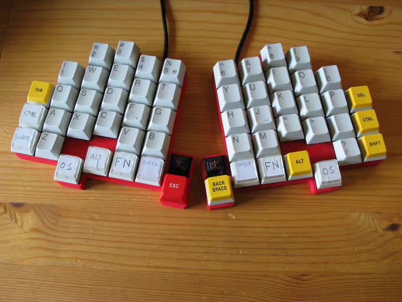 Finished keyboard
This article featured on Hackaday.
In this article:
One day, it must have been around , Jeroen Domburg (also known as Sprite_tm) showed me his IBM Model M keyboard. He had recently gotten his hands on a couple of those and use one as his main keyboard now. Since he had a couple more, he gave me one to try as well. I liked the '80s design and the robustness and without giving it much thought I started using it as my main keyboard. A while later I used a standard keyboard again, the kind I had used for so many years, and realized I liked the Model M better. The key movement seemed more smooth to me. The keys of the cheap plastic keyboard seemed to wobble and squeak, which I had never noticed before. I also seemed to make fewer typing errors when using the Model M. This was probably my first step into the world of keyboards.
Since the Model M keyboard is quite an old design (introduced in ), it used a PS/2 connection to the computer. However, my computer didn't have a PS/2 port, so I bought a PS/2 to USB converter. This worked well for years and I mostly forgot about it. But one day, a few years later, I was looking for something to do. Remembering the converter, I decided to upgrade my Model M with native USB support. After all, where is the fun in using a bought PS/2 to USB converter when you can build something yourself? While searching for DIY keyboard conversions I came across two internet forums dedicated to computer keyboards: Geekhack and Deskthority. There are actual sub-forums for keycaps, ergonomics, reviews, diy and whatnot. There are discussions about switches and keyboard layouts. A whole new world opened up for me. I started reading a lot more about improved keyboard layouts, ergonomic keyboards, keyboard conversions and also people building their own keyboard from scratch.
Some time later, I came across the Humble Hacker keyboard, by David Whetstone in a geekhack thread. This design opened my eyes for radically different key layouts. The arrow keys and several other keys were moved to the center of the keyboard. It didn't have a spacebar but several thumb keys. I could see how this would be an improvement. The keyboard was also very nicely built. Nothing looked like it was hacked together, on the contrary, it looked shop-bought.
In the mean time we got some new computers at the office. Those usually come with a standard keyboard, but this time the keyboard design was different from what we were used to. The sides of the enclosure started almost exactly where the keys ended. The border around the keys was completely gone. This sort of sleek design is known as 'form follows function'. Arrange all the keys, then fit the enclosure tightly around it. I really liked the looks of this keyboard and filed this in my head for when it might come in handy.
Another build that really inspired me is the Key64 by Nestor A. Diaz. This keyboard also had features I had never seen before. There was a separate cluster of thumb keys and the keyboard was literally split in two halves. The build was not as clean and well-polished as the HH1, it was even better. It looked like something I could do myself!
Some years later the Key64 also inspired the ErgoDox keyboard project.
All this reading was very inspiring and I started wondering if keyboard building is something I wanted to do myself. When you design you own keyboard, the possibilities are endless. Actually, there have been some things about my current keyboard that started to bother me, and this could an opportunity to improve upon their design. Now that you are reading this article, you know which choise I made.
If you would like to see some more interesting keyboards, there is quite a collection over at ∑XAH's keyboard blog and keyboard heaven. Also I recently came across the Dactyl keyboard and en ergonomic keyboard build by an ergonomic keyboard build by Jens Wilhelm Wulf.
Okay, now that I have decided to design and build my own keyboard, where do I start? I would like to try to combine the best features of the keyboards I had seen and improve where possible.
I liked the way that on several keyboards keys are in columns instead of rows. This is sometimes called matrix layout. The staggered layout of a standard computer keyboard has always struck me as odd. The fact that the next row of keys is always shifted a bit to the side is a relic from the typewriter with their cumbersome mechanics. In a modern world there is no need for this other than sentimental value. If it were actually good for ergonomics I would expect both hands to move inwards or outwards for the next row, not both to the same side. This issue is nicely solved with a column layout.
While the columns of the Key64 are straight, the rows aren't. It's quite logical once you think about it. When I place my hands in front of me, my fingertips are in two semi-circles. This is nothing like the straight row of keys on a typical keyboard. I have to move all my fingers to fit on the straight home row of a typical keyboard. Keys should be under my fingertips, not the other way around. This issue is elegantly addressed with slightly curved rows of the Key64. Later I came across more designs that did this.
Several keyboards also had a bit more distance between the hands than on a straight keyboard. Some keyboards were even split in two separate halves. If you look at your wrists while typing you know why this is. You have to bend your wrists outwards quite a bit to fit your hands next to each other on the straight home row and by doing this you restrict blood circulation. A keyboard should fit your body, not restrict your body. So my keyboard design became a split-layout.
Another improvement is in they keys that are not on it. There are a lot of keys I can do without. Caps lock for instance, or scroll lock, or insert. When you are a bit more daring, you can also lose the numpad. Some minimalistic designs also ditch the function keys. One of the clever ideas in those minimal keyboards is the use of an 'fn' key. When you press and hold fn, all keys get a different function. Some laptops have this too for setting screen brightness etc. This feature is incorporated in my design as well. For instance fn + i, j ,k, l (right-hand home row, home position) becomes the arrow keys. It is like having the 'inverted T' arrows right on your home row. You don't have to move your right hand anymore when you need the arrow keys. This is a huge improvement over the typical keyboard design. Fn + number keys become the function keys. A lot of other keys have moved to the fn-layer as well.
Making the keyboard more compact also enables you to move your mouse closer. This is, once again, good for ergonomics.
You have two thumbs and only one key they ever press; the spacebar. This seems like such a waste. There are a couple of keys that would be handy to have withing your thumbs reach. Traditionally there is only the spacebar, but how about enter? I use enter almost as much as space. Or how about backspace, or escape (which I use a lot as a Vim user), or the new fn key. After a bit of experimenting I also moved alt and the Windows key to the thumb clusters.
From a more philosophical viewpoint I like the minimalist approach. Also the almost completely symmetrical design in terms of key placement and function feels right. Why should one hand do more work than the other?
A lot of keyboards, both commercial and DIY, seemed to use the Cherry MX switches. Both switches and keycaps are reasonably easy to obtain. This seemed a good choice for my keyboard as well.
Since I'll be moving a lot of keys to a new position I had to decide what goes where. To get some statistics about the usage of every key I wrote a little program that records all my keystrokes and reports exactly how often every key is used. After running it for a couple of days I got the following top 5: Space (3839 times), e (2661 times), Enter (2259 times), left Control (1906 times) and Backspace (1743 times). These are my personal statistics, I have no idea if they're anything like average.
The statistics helped me to make a design for the layout. Control is the most used modifier, therefore it should be on the homerow. Enter and backspace are used a lot as well, so they should be easily accessible. All modifiers should be on both halves, one for each hand, on an easily accessible location. The figure on the left shows the layout I came up with. Top half shows the normal key mapping, bottom half shows the key mapping with Fn pressed.
To get a feel for the new key placement, I bought a programmable matrix keyboard. It's a Tipro MID128 fully programmable keyboard with 8 rows of 16 keys. It is designed for point of sale applications and came with software to assign any function to any key. Unfortunately the software only runs on 32bit Windows and requires a physical PS/2 port on your computer. The software uses some non-standard PS/2 commands and low-level voodoo to do the data transfer to the keyboard, hence the specific requirements. Being the open source nerd that I am, my computer doesn't run Windows. I do not even own a copy. Also none of my machines has a PS/2 port. This was a bit of a setback. Luckily my girlfriend had an old laptop running a dual boot with 32bit Windows Vista and a PS/2 port, so I used her laptop every once in a while to program a new layout. Once the layout is programmed into the keyboard, it works on any OS and also via USB converters. I have been tempted to reverse engineer the PS/2 data transfer protocol and write open source software for it but realized I'd better finish the new keyboard first before I start yet another project.
I quickly got used to the matrix layout. It felt more logical and keys like 'y' were a lot easier to reach with the correct hand. Getting used to the new location of the modifiers and the symbols on the fn layer took some more time. Also I noticed myself repeatedly making a the same typing error. I only ever used my right-hand thumb for space, or so I thought. The exception is when I can type a whole word using only my left hand, like 'database' or 'test' (or 'stewardesses', with I never actually type). Then I use my left-hand thumb for space. Since the key under my left thumb is now enter, the intended space turns out an enter. This little quirk may tell more about me than about the layout, tough.
Key switches and key caps
The Tipro keyboard came with Cherry MX black switches installed. Those are quite heavy to depress and have no noticeable click. Other versions of this switch exist, all with different color coding. For instance, there are Cherry MX brown switches which have a tactile (feelable) click and the blue switches have both tactile and audible click. I didn't like the lack of click of the black switches, so I desoldered all key switches from the keyboard. On the places where I would need them, I soldered brown switches. This left a lot of empty places on the keyboard but I didn't really see a problem with that. The brown switches came from a Compaq keyboard I bought on Ebay and cannibalized for parts. The brown switches suited me a lot better than the blacks. Compared to the Model M keyboard, they are a lot lighter and more quiet. After some time and a bit of experimenting I added rubber dampening rings under the keycaps to keep the noise further down.
The programmable keyboard came with a lot of funny keycaps, like 'total', 'receipt', 'manager mode' and a couple of relegendable keycaps. Those have a clear top that you could stick your own label under. With those keycaps I could make all the missing labels such as 'fn'. Unfortunately the keycaps all had a completely flat top. My fingers kept sliding off the keys, so used the Compaq keycaps for the letters and numbers. The keyboard started to look like a funny mix of white Compaq keycaps, brightly colored POS keycaps and some hand written labels.
It felt great to be able to test my new layout at home on my own computer. On the other hand, at work I still used the keyboard that came with the computer. So after a couple of weeks I decided to order a second programmable keyboard for at the office. My colleagues were a bit surprised when they first saw it, but it's a great conversation starter. Some regarded it as only a little odd and started typing away like on any other keyboard. Some others didn't know what has gotten into me but kept away from the keyboard in case it was contagious.
One of the things I would like to replicate in my design is the curved rows of the Key64. To get some meaturements for the curve I put my hand on a sheet of paper, fingers slightly curved, and marked where my fingertips were. The curve I just drew turned out a bit more pronounced than on the Key64 design. I wondered if my fingers were longer or shorter then usual, but I decided to use my own curve nevertheless. For testing I placed some keycaps on the curve and tried to get a feel for the placement. It turned out hard to mock type without moving the keys sideways. The angle on the thumb keys seemed wrong, so I turned the caps around. The symbols are now upside down, but it feels a lot better.
I have never done any 3d design in my life, so designing a complete keyboard seemed challenging, to say the least. The 3d Design programs I have seen looked very intimidating and complicated. I didn't know where to start. Luckily I came across OpenSCAD, a scriptable CAD program. This was a relief. Scripting is something I can handle. It suited me a lot beter than using any other 3d drawing software. If it weren't for OpenSCAD I might have given up on designing the enclosure and and just used the bare circuit board.
I made some 'modules' for a single key and for a piece of border. You can use those modules when you make up the whole keyboard. You can transpose, transform, mirror, make rows of keys and if you don't like the design, tweak some parameters. Since both halved of the keyboard are mirror images of each other, I only have to design one. When I need the other half I can just mirror the design.
I don't have a 3d printer by choice. Most people with a reprap or similar 3d printer seem to spend more time fixing the printer than actually printing objects. Besides, the resolution is low, the printers are slow and expensive and what do I ever need to print? I obviously never imagined building my own keyboard. Lucky for me, and all other 3d printerless people, you can have your designs printed on a professional printer and shipped to your home via numerous websites. I used Shapeways for this. They are reasonably affordable, high quality, high resolution and print in all kinds of funky materials and colors. Simply upload your design, pay, wait a few days and you'll receive a physical copy of your own design.
When I finished the 3d design, I only had the right-hand half of the keyboard printed. This was all I needed for testing and if somthing turns out to be wrong I only have to have one part reprinted. Once this half works well, I will order the other half.
Shapeways can print in a variety of paterials, however I simply choose nylon. This material is lightweight, sturdy, easy to cut and cheap. They can dye it for you so I had it dyed bright red.
Mechanical design is one half, electrical design is the other half. All the key presses must somehow be transfered to the computer. I have never designed electronics for a keyboard before or built anything connected to USB, but, like the rest of this project, this seemed like a fun challenge.
Every keyboard has a controller. This processor reads the keys, translate this to messages about key presses and releases and sends those messages to the computer. For most modern keyboards this is usually over USB. The computer only sees a generic USB input device. There is no difference between this keyboard or any other USB keyboard, as far as the computer is concerned. The controller for this keyboard is an Atmel ATMega328P. The processor is connected to the key switches on one side and to the computer on the other side. Since the processor has no onboard USB this is emulated in firmware with vUSB.
On this protoboard you can see the microcontroller, 12MHz crystal, isp header, I²C connector, debug led and programmer. There are some more components on the bottom.
There are a lot of keys on a keyboard. Connecting all of them directly to the controller would require a lot of wires and a lot of inpupt pins on the processor. Luckily there are other ways of connecting all those key switchs. One of the most common techniques is multiplexing (muxing). The key switches are wired in a big matrix. The controller drives one row at the time and reads all columns to see if a switch is pressed on the intersection of that specific row and columns. While this works fine when a single key is pressed at a time, you may run into trouble when more than one key is pressed at once. The problem is that for some combinations of keys, it looks to the controller like some other keys are pressed as well. This phenomenon is known as 'ghosting'. In most keyboards the columns and rows are spread out over the board in such a way that ghosting almost never happens. A remedy to completely cure this this problem could be to throw in some more electronics. When you add a diode in series with every key switch, the ghosting problem is solved. Unfortunately the Tipro MID128 keyboard I used to test the key layout has a lot of noticable ghosting. In fact, it appears so often I get really fed up about it. There is very little you can do about this afterwards, it can only be solved in the design. Because of the annoying ghosing problems with the Tipro keyboard I wanted to make sure my own design would not have this problem.
There are also several other ways to read all key switches. For this keyboard I choose to use I/O expanders. The I/O expanders have a lot of inputs each and are connected to the processor via a simple 2 wire bus. Each expander gives me 16 extra inputs. So every switch is directly connected to one of the inputs on one of the I/O expanders. The I/O expanders are in turn connected to the processor and this solved the pin count problem. This approach is similar to using shift registers, but has some more advantages. The used I/O expanders are Microchip MCP23017, with 16 GPIO pins each and configurable pull-up. The I/O expanders are connected over I²C to the processor. Every I/O expander is set to a unique address, so they can be addressed individually.
While you could connect everything inside the keyboard with point to point wiring, a more elegant and profesional solution would be to make a printed circuit board. This neatly connects everything and once all the key switches are soldered on, the board also adds to the overall stiffness of the construction. Designing a pcb is not too different from designing the enclosure. You need to know exactly where everything goes mechanically and then just draw in the electrical connections. For this design I used gEDA pcb, part of the GPL'd Electronics Design Automation tools. Pcb is a simple, easy to use pcb design program. It might not be as advanced as some of the commercial software, but it is completely free, open source and without any artificial (pin) limits. I used this software before for several other projects (like the tikkenteller, a phone cost registration system) so I stuck with it for this project.
Since the keyboard consists of two halves, one for each hand, we need two circuit boards. Both halves of the keyboard enclosure are mirror images, so I wondered if it would be possible to make a reversible pcb, to use the same design for both halves only flipped over. This would not only save on pcb production costs (multiple copies of a single design is usually cheaper than multiple designs with a single copy each), but be an design challenge as well. The keyboard enclosure is very compact and most of the surface of the PCB is already taken up by the key switches, so there is very limited space for anything else on the circuit board. Using surface mounted parts helps to make the most of the available space. Unfortunately this space was taken up by the I/O expanders. There was no more room for the processor. So the processor moved to a separate PCB. Since there are only 4 wires needed between the processor board and the keyboard half (vcc, gnd, sda and sck), this is not much of a problem. Maybe I will integrate the processor in a future prototype.
To be able to physically fit the pcb into the enclosure, all surface mount parts need to be at the bottom of the pcb. There is just no room on the top. Only the pcb bottom for one half of the keyboard would be the pcb top for the other half. So I designed footprints for all smd parts on both the top and bottom side of the pcb. Only populate one at the time. There is a slight difference between top and bottom footprints tough. Every I/O expander needs to have a unique I²C address, so they can be individually addressed by the processor. The address is set by pulling 3 pins on the I/O expander either high or low. So the 'top' I/O expanders are set to one address and the 'bottom' I/O expanders are set to another. Another top / bottom problem is that the footprint of the key switches is asymmetrical. The pin on the righthad side of the switch sits closer to the top and the pin on the lefthand side sits closer to the side. For this I made a special double-sided Cherry MX shape for the pcb software. In this shape are holes for both top and bottom mount. Another challenge was that part of the measurements for the pcb are in metric, but the rest is imperial. For instance the enclosure dimensions and the spacing between key switches is in millimeters, but the switch dimensions are in inches.
For the processor I thought of something easier (and conciderably cheaper) than designing and producing a PCB. I would repurpose one of the cheap USBASP boards from from Ebay. Those are devices ment to be used as AVR programmer. There is a processor, crystal, voltage regulator, USB interface, led, headers and all the other things I'd like to have on the processor board. The complete USBASP is cheaper on Ebay than buying parts, let alone having another PCB made. All I'd have to do is rewire some pins and flash my own firmware.
As you can see in some of the pictures, I used prototype board for the processor. I can't remember exactly why I didn't use the USBASP.
With the PCB design finished, I had to get the actual PCBs. I have home-brewed some PCBs in the past using toner transfer. You print the design on a sheet of special paper using a laser printer. Then you tranfer the toner from the paper to the pcb material using a clothes iron. If everything works out, you have the design stuck to the PCB material. This worked for me before, but not this time. I made several attempts with different printers, different types of paper and different types of PCB, but nothing stuck. In the end I gave up and, just like the 3d print, decided to order online.
There are many places that will produce PCBs for you. Some are fast, some are cheap, some are high quality, some are not. If you order in China you will save on production costs, but it'll take longer and it might not be the best quality. Saving costs would be nice, but more important to me is that it is produced with respect for the workers and the environment. Chinese PCB manufacterers tend save costs by underpaying their workers and dumping chemical waste in the environment. I'd rather spend a bit more on a PCB than allowing this to continue. With a bit of searching and comparing I decided on Jackaltac. As far as I can tell their PCBs are produced in the UK.
Even tough I only had one side of the enclosure printed, I decided to get 2 copies of the PCB to save on shipping.
The enclosure and the PCB were ordered at roughly the same time. With a little over a week of producing and shipping I had plenty of time to worry if it would all fit together. Would the key switches fit into the square holes in the enclosure? Would the switch location on the PCB match the holes in the enclosure? Would the PCB actually fit into the enclosure? Haven't I made an error with the mirrored / double sided PCB design? Or any metric / imperial conversion errors?
Once everything arrived I gave it a try. Imagine my surprise when everything fitted perfectly! The Cherry MX key switches fitted snugly in the holes of the enclosure and the pcb fitted exactly within the sides of the enclosure. No measurement errors or conversion errors, as far as I could tell. I should have made this my job.
First thing to solder were the I/O expanders. Soldering surface-mounted parts can be tricky, but with a small tip on the soldering iron, a steady hand and plenty of flux it worked out fine.
Next up were the key switches. This part was easy; fit the pcb in the enclosure, snap in one key swith, solder it onto the PCB, snap in the next switch, solder it. Repeat until you run out of holes.
Now that the switches are mounted, I fitted some spare keycaps. Now I could finally try out the design for the first time. It's great to see the 'wave' of keys fitted exactly under my fingertips. I can't wait to start typing on this new keyboard.
I still only had one half of the keyboard. I resisted the urge to immediately order the second half and decided to focus on the firmware.
Without firmware the keyboard would be useless. It is the 'glue' between the electronics and the USB connection with the computer. Actually firmware is fancy word for software running on a dedicated device. Writing firmware not that different from writing software for your computer.
Instead of starting development on the AVR, I decided to do some quick testing on a Raspberry Pi first. One of the advantages of the Raspberry Pi is that it's a full-blown Linux system so you can make use of all the programming and debugging capabilities. It also has onboard GPI0 and I²C, just like the AVR. Once the software works on the Raspberry Pi, I will port it to the AVR.
Funny sidenote about ths particular Raspberry Pi B+ is that I have recently bought it for 20 cents on the local flea market on King's day. It works just fine and even came with an enclosure and 8 GB flash card.
Using I²C in Linux is relatively simple, just open /dev/i2c-1. So with a little bit of C code I should be able to read the key switches. Unfortunately this didn't work. No matter what I tried, the I/O expanders didn't respond at all. When I couldn't find any errors in the C code, I started checking the electronics. As it turned out I had mis-read the datasheet and the reset pin of the I/O expander is actually low active. Therefore it must be pulled high in order for the I/O expander to answer on the I²C bus. When pulled low the I/O expander is in reset and nothing happens. So I desoldered the offending I/O expander /reset pin and lifted it slightly off the pcb. With some wire I connected it to VCC on another pin. The fix worked and everything behaved as expected now. I was able to read the status of all key switches without any more trouble.
With a bit of fiddling, and the help of uinput, I was even able to make the keyboard work as if it were attached to USB. Now the whole OS can use this keyboard instead of only using it in my program. Unfortunately the Raspberry Pi does not support USB device mode, so I was still unable to use the keyboard directly on my main computer. I thought about using synergy to transfer my keystrokes from the Raspberry Pi to my main computer, or make something using xdotool and netcat. On second thought I decided to direct my energy elsewhere.
With the keyboard working on the Raspberry Pi it was time to make it work without it. I would like to get it up and runnning on an Atmel AVR, the same type of processor I used in many other projects. This presented some challenges as I had never used either I²C or USB on an AVR before. This would also be my first time writing in C in instead of in assembler for this processor.
The ATMega AVRs have an I²C controller on board (called two wire interface). So instead of bit-banging the protocol yourself you could just let the controller take care of it for you. I carefully read the datasheet and looked at some code examples. How hard could this really be?
As it turned out getting the I²C to function was a lot more work than I expected. The I²C on the Raspberry Pi had just worked, once I had fixed the PCB error. But no matter what I tried, I could not make it happen on the AVR. Instead of reading the contents of the I/O expander I only got random data. After a couple of frustrating evenings trying to debug the software, I decided to get the logic analyzer out and take a look what's going on.
I ran the working code on the Raspberry Pi again, this time sniffing the I²C communications with the logic analyzer. Then I sniffed the communications with the non-working code on the AVR. Comparing both I²C dumps revealed the difference. It turns out the Raspberry Pi sent a STOP after every packet. The AVR code did not send a STOP but only a repeated START at the start of the next packet. According to the I²C specifications both should be valid and actually the latter is preferred. However, once I added the extra STOP in the AVR code I²C finally worked. Now I was able to read the I/O expanders. After days of being stuck it's great to finally make some progress.
The logic analyzer I used is an Open Logic Sniffer, designed by Dangerous Prototypes and Gadget Factory, running the Alternative OLS client. It is cheap, open source and helped me debug several projects before.
Next step is the USB. The nice people over at Objective Development have made vUSB, a software USB implementation for AVRs. With this library it should be possible to run the entire keyboard controller on an AVR with very little additional hardware. So I looked at some code examples and gave it a try.
After a while I had hacked together some code that should send keystrokes over USB. But whatever it sent, not the keystrokes I intended. It seemed to be random letters and symbols. Once again I spent a couple of hours trying to debug the code. When that didn't fix the problem I started wireshark to have a look at the USB communication.
Wireshark revealed that indeed random data was sent in the USB packets where the keystrokes should be. The USB packet itself was valid, so the problem was limited to just the few bytes of payload that held the keys and modifier data.
When I sent a single predefined letter, it all worked, but when picked the letter from a static lookup table I got random data instead. The problem seemed to happen every time I read from the array that held the keymap. This array is 64 bytes long and read-only, so I wrote it to program flash instead of RAM. AVR-Libc has the PROGMEM macro defined for this. However, reading from this array only seemd to return garbage. Finally I found the solution in the AVR-libc manual. Apperently C has some trouble with the Harvard architecture of the AVR so you need to do an extra trick when you read from program memory instead of RAM. Instead of the usual key = keymap[i]; you do key = pgm_read_byte(&(keymap[i])); and the problem is solved. Once you know the answer it all seems so obvious, but these things take days to figure out.
With the firmware mostly finished I could finally give the keyboard a try. It was awesome to press a button on my self-desgned, self-built keyboard and watch a letter appear on the screen. But with the other half of the keyboard missing it was hard to really start using it. So I ordered the other half of the enclosure. This is what I have been wanting to do ever since assembling the first half.
The second half was assembled quickly and without any problems. The I/O expander reset pin was modified in the same way as before. Also the firmware accepted the extra keys on the first try. Now I could finally do some real typing on the complete keyboard.
Not all keys were implemented yet. The letter keys and modifiers mostly worked, but the 'fn' layer was still missing. So I set to completing the firmware for the keyboard on the keyboard itself. Isn't that something special, writing the firmware for this keyboard on the keyboard itself?
Flashing the keyboard firmware became a bit tricky though. To flash the keyboard you have to unplug it from the computer and plug in the programmer. Now you have to enter a command to start the flashing, but you have no keyboard plugged in. My previous keyboard is still within arms reach, but all the keycaps are taken off to use on the new keyboard. So I decided to enter all commands in advance, using the new keyboard, and then set a timer for a couple of seconds before the commands would be executed. This would give me a window to unplug the keyboard and plug in the programmer.
This trick worked nicely while adding some more keys to the firmware, until I maded an error in the code. The code compiled and I flashed it into the keyboard. It was when I plugged the keyboard into the computer when I nodiced the 'fn' was stuck on. All I could do was type some symbols and arrow keys. It took some creative copy-pasting to start the editor, find and fix the error, compile and re-flash the keyboard. But I do like a challenge, otherwise I wouldn't have started this project (or just walked a meter to dig out another keyboard, in this case).
When typing on the keyboard I immediately started to notice all the differences with the keyboards I was used to. For instance I like the spots where finger travel had decreased, such as the index finger rows. On the other hand, I have to get used to the spots where finger travel has increased. This is most noticable when reaching for the shift key, wich is a full row lower than before. The 'Q' and 'P' columns are shifted down exactly one key. This caused lots of typo's before I got used to it. Also where space and enterused to be on my previous keyboard, are now escape and backspace. This also led to some confusion. I'm already used at the 'fn' layer, so no surprises there. This is one of those things I really miss when typing on any other keyboard.
Since the keyboard is so lightweight, it slides a bit over the desk when you're typing. I have stuck some rubber feet to the bottom, but it keeps sliding. Both haves can move around freely and you can have quite some ditance between them, but I mostly use the keyboard with both halves immediately next to eachother at approximately 30 degrees angle.
I have noticed that the keyboard does not work in bios. Also, the keyboard sometimes freezes for a couple of seconds when you press keys too fast. This sometimes happens with a key depressed which can be quite annoying, especially when the key happens to be backspace. These issues might be fixed in a future firmware. It would be a good idea to also add some debouncing for the key switches. Now that the switches are getting a little older, bouncing increases.
After a couple of months the lefthand fn key started to fail. You had to press it really hard to work. It turns out I forgot to solder one of the pins of the key switch. With the pin properly soldered the problem went away. I haven't noticed any other soldering errors.
So far so good. Let's see how this keyboard will last as my main keyboard at home.
What would such a keyboard cost you? Good question, let me see if I can give you an estimate. Most numbers here are rounded or otherwise educated guesses. All prices include tax and shippping. Most parts are sourced from Ebay or came from the geekhack and deskthority marketplace.
My first buy was a Tipro keyboard to test the layout. This cost me 40 euro. I then traded some keycaps for others. This only cost me shipping. A second Tipro keyboard cost me another €40. Keycaps came from a donor keyboard which cost me €65. PS/2-to-USB converts cost me around €15. Then came the 3d prints. First I ordered some test bits to check if my sizing was correct. These bits cost me €30. With the sizing settled I then ordered the full enclosures, one at the time. These cost €35 each. Then came some electronics. The two PCBs cost me €70. I/O Expanders cost me €20. It turned out I ordered the wrong model at first so had to pay postage for returning them as well. I ordered many key switches that were used in the Tipro keyboards and the finished product, and yet another set of keycaps for testing. Most other parts came from my parts bin, such as the Raspberry pi, AVR, AVR programmer, logic analyzer, prototype board, headers and other miscellanious parts. Also, most of the parts I bought were used in development rather than in the resulting product. Selling off the surplus parts could make up for some of the costs.
As for the hours I put in, I never kept a record of those. My best guess would be that I spent several hunderd hours designing, writing firmware, testing, debugging and writing this article. And there is several more hours just thinking about the project, discussing it with friends. All in all, it's probably a fair bit more than I care to admit.
So that totals to around €400, plus hunderds of hours for developing a one-off, custom keyboard. If you were to build another copy of this keyboard, you could probably do that for around €200 in parts, using the same suppliers. If you have cheap access to a 3d printer and order cheap PCBs, you could probably get that down to around €100. With a well-stocked parts bin you could go even lower. Putting it all together should not take more than a couple of hours. Proper mechanical keyboards retail for 100-200 euro, so the price is actually not that bad. Unsurprisingly most of the costs are hours spent in development.
Now that the keyboard build is finished, one can't help but starting to think about some improvements. Here is a list with some of the things I have thought about for a future prototype.
Joystick mouse. My Lenovo Thinkpad laptop has this lovely little joystick mouse, called TrackPoint. I wonder if it would be useful to integrate one in my own keyboard. This would break the symmetry of the two halves design and make it explicitly right-handed (or left-handed). There will have to be mouse buttons as well. All in all I'm not sure yet, but it's an option.
Improved thumb-key layout. The thumbs-keys currently are at a bit of an odd angle. Your thumbs always seem to hit a corner. Also I keep mixing up some of the thumb-keys, typing backspace instead of space an escape instead of enter. I would like to have the thumb-keys more like a semi-circle and moved a bit more towards the center of the keyboard. Jesse Vincent has done exactly this with his beautiful Butterfly keyboard (now called keyboardio).
RGB backlight, just because I can. It serves no function other than awesomeness. As far as I can tell here has not yet been a diy keyboard with RGB backlight, only commercial ones. I just came across the fsociety keyboard on Hackaday. It is a truly diy keyboard with, among other features, RGB backlight using WS2812b modules.
Cherry recently introduced MX RGB switches. Those are similar to the existing MX switches, but with completely transparent housing. Just place an 0805 SMD RGB led on the pcb and mount the switch over it. The light is spread by the switch and you get a nice glow under your keycap. A complete datasheet is hard to find, so I requested one from Cherry and put a copy in the downloads directory of this article.
Having the leds addressable per key swith would of course be best. There are several dedicated led driver ics such as the Texas Instruments TLC5954 48 channel constant-current led driver, or the Panasonic AN32181B 12x12 led matrix driver used in the Corsair Vengeance K70 keyboard.
Plate-mounted key switches. In several keyboards designs the key switches are snapped into square holes in a steel top plate. This makes a keyboard both very sturdy and nice and heavy. In addition to the steel top plate, there could be a steel bottom plate as well. This, once again, adds to the weight and stiffness. The Tipro keyboard I used for prototyping the key layout has steel plates both on the top and on the bottom. The resulting keyboard is quite heavy, but really sturdy and it never slides over my desk. Cutting steel might also be cheaper then 3d printing the whole enclosure.
Charlieplex the switch matrix. Instead of using I/O expanders I would like a Charlieplex matrix. While the I/O expanders work fine, it might not be the most elegant solution. Also, removing the I/O expanders from the PCB design would free up some space wich could be used for other things instead, like the AVR or an RGB led controller.
Use a processor with hardware USB controller. This would be a more elegant solution than the software hack currently used. Atmel Microchip makes a couple of AVRs with USB hardware such as the ATMega32U2. Those don't have I²C hardware, wich is one more reason to abandon the I/O expanders.
Last but not least, the microcontroller should be integrated in the keyboard itself. This would make the whole thing more compact and more elegant. It might even be a good idea if both halves of the keyboard get their own processor. The processor would handle the switch matrix and backlight for that half. One of the halves gets a USB port for connecting to the computer. Both halves still need to be connected together in some way.
The keyboard in this article is developed using free and open source software and hardware where possible. The enclosure 3d design is done using OpenSCAD. The PCB is designed using gEDA pcb. Firmware is written using Vim, compiled with GCC and programmed with AVRDUDE and USBasp. For debugging I used the Open Logic Sniffer with Alternative OLS client and Wireshark.
In turn this design and article are released into the public domain. You can find all relevant files in the downloads directory of this article.
While I did enjoy the process of building the keyboard, I'm glad it's finished. Now I can finally use the thing as an actual keyboard. It is and the build has taken me over 4 years on and off to complete. It was a lot more work than I expected and finishing projects is not one of my strengths. But I made it and I'm now happily using the keyboard on a daily basis. I love showing it to anyone who is interested. Most of this article is written on this very keyboard.