EVBox charger autostart module
Project – | Article by Maarten Tromp | Published , updated | 4159 words
Introduction
In this project, I designed a small autostart module for EVBox G2 and G3 chargers. It replaces the modem, allowing the chargers to operate stand-alone without the need for a backend that no longer exists, bringing them back to life and preventing them from becoming unnecessary e-waste.
Buy a ready-made and fully-tested autostart module.
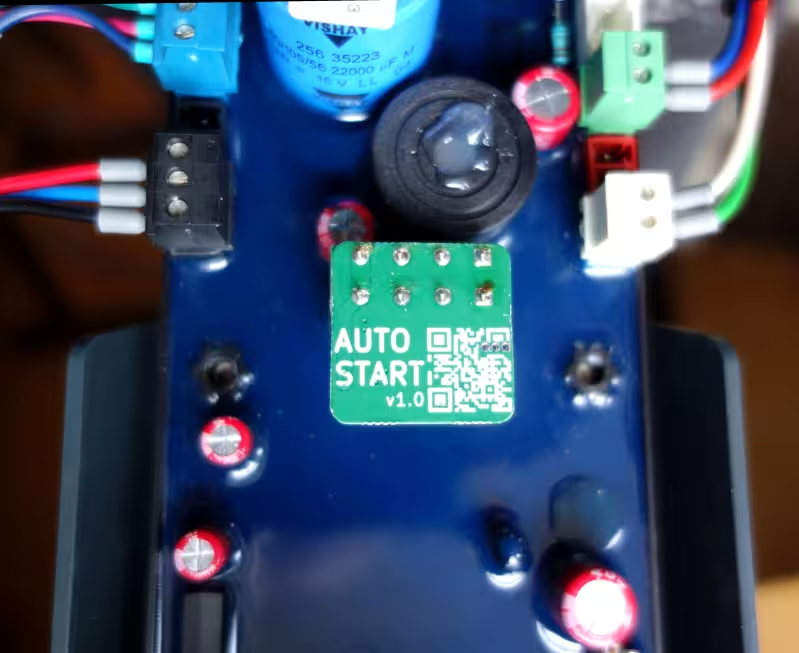 Autostart module
In this article:
In a previous project, I turned my managed EV charger into a stand-alone unit using a Raspberry Pi. The original goal was to create a microcontroller-based autostart module, but I had forgotten about that once the project reached a point where I could charge my bike.
When I recently received an email asking for simple, step-by-step instructions on how to make an EVBox charger stand-alone, the idea of a simple autostart module came back to me. But this time, I did make it.
This project is increasingly relevant, as the manufacturer, EVBox, has all but gone under. Their EverOn backend—ironically named—is now offline, rendering all chargers that depend on it useless. The autostart module could potentially save many perfectly good chargers from the landfill.
EVBox G2 and G3 chargers consist of two main components: the charger itself and a modem. The charger does not make any decisions on its own, it leaves that to the modem. The modem responds to some requests itself, but needs to contact the EVBox EverOn backend for others. This is the reason why everything stopped working when the EverOn backend was shut down.
While is it possible for the charger to work with a different backend, many people have not changed this. It is still possible to do so, see the Reversing the EVBox ChargeStation Tool project, but it requires some technical know-how, making it inaccessible for most charger owners.
The autostart module replaces the modem and provides everything the charger needs to function, without requiring an actual modem or backend connection. It effectively turns the charger into a stand-alone autostart unit. No subscription or backend connection is required.
Only a subset of the charger’s functionality is implemented in the module. Features such as metering, remote control, and authentication are not supported. The module is designed specifically for EVBox G2 and G3 chargers, produced between roughly 2013 and 2023. If your charger resembles the photo on the left, it is supported.
The module is a drop-in replacement for the modem. To install it, open the charger, swap the modem for the autostart module, close the charger, and you are ready to go. You can find the complete installation manual here.
The hardware for the module is quite simple and requires only a small number of components. Charger-specific details are documented here.
As the software is not particularly complex, I selected a suitably small microcontroller. The ATtiny202 features a single USART, internal clock, 2 kB of flash (program) memory, and 128 B of RAM. It is accompanied by a programming/debugging header.
Communication with the charger uses RS-485, so the design includes a RS-485 transceiver, protection diodes, and termination and bias resistors. The original modem used an Analog Devices ADM3485, which is an excellent transceiver, so I used the same one.
To step down the voltage from the 12 V rail, an AMS1117 voltage regulator is used. The circuit draws very little current (only a few mA), making a linear regulator the simplest solution. A tantalum capacitor provides output stability.
The module connects to the charger via a Phoenix Contact four-pin female pluggable terminal block.
As EV chargers are typically installed outdoors, I selected components rated for at least −40 °C to +85 °C.
The schematic diagram is a textbook implementation of an RS-485 interface, a linear regulator, and a microcontroller. In this specific design an input capacitor for the regulator is not required, as it is located very close to the main filter capacitor within the charger. Local decoupling for the microcontroller is similarly unnecessary, since it is very close to the voltage regulator output capacitor.
Due to the low component count, and my fondness for optimisation, I aimed to make the module as compact as possible. The result is a 22 × 22 mm PCB, matching the width of the charger connector. There is a ground pour on both sides of the board, with via stitching to improve performance in a noisy environment. The PCB was designed using KiCad.
The starting point for the software was the Python ChargePoint implementation from the earlier stand-alone project. I re-implemented a minimum viable CP in CircuitPython, stripping away modularity, abstraction layers and a cache of all possible commands. This reduced the implementation to just a handful of essential frames, and some logic when to send which frame. I tested this version on the Raspberry Pi Pico with a WaveShare RS-485 board that was left over from a previous project. While this made for a convenient proof of concept, for production use I wanted something more robust. So I rewrote the software in C, compiling it with avr-gcc.
The microcontroller I had chosen has a very small amount of RAM—only 128 bytes—so the software had to be carefully optimised for minimal memory usage. This turned out to be fun to do. As incoming frames are larger than the total amount of RAM, it was not possible to store an entire frame for validation and parsing. Instead, I implemented streaming validation and retained only the few frame bytes that were required for decision making. Since most outgoing frames are static, these are stored in flash memory (PROGMEM) rather than in RAM.
At the last moment before ordering parts I switched the MCU from ATtiny202 to ATtiny402, which has double the flash (4 kB) and ram (256 B). I'm happy I did so because the compiled firmware turned out around 3 kB in size. Attempting to squeeze it into 2 Bk flash would mean a lot more optimising and/or cutting some corners.
Accompanying the firmware are unit tests, integration test, and regression tests. There now are many more lines of test code than firmware code. Writing the tests really paid off, catching so many errors and edge cases. This is also where AI became useful; creating unit tests and finding gaps in test coverage. With the passing of tests, my confidence in the firmware grew.
I think I wrote the proof of concept code in a day or two, but the C firmware and unit tests took me over a month, making sure it's solid and covers all edge cases. I'm not usually this thorough in my own projects, which usually end in the proof of concept stage.
PCB production is, once again, handled by PCBWay (affiliate link). There is simply no way that local fabs can match their pricing. I had also requested a quote for assembly, but this turned out to be more expensive than I had hoped. PCBWay generally offers very competitive component pricing, but a few of the components were surprisingly expensive. Together with the setup fee, this made assembly prohibitively expensive for such a small batch. So over to plan B; sourcing components and handling assembly myself. Obviously I was unprepared for what came next.
In fairness, the quotes I had requested were for 5, 10, and 20 units — not 50. The per-unit cost at larger quantities would likely have been considerably lower, making the comparison less straightforward than it first appeared.
I spent the following days searching Conrad Electronic, Farnell, DigiKey, and other relatively local suppliers, before turning to eBay, AliExpress, and AliBaba. Some components proved difficult to source at a reasonable price — or to source at all with certain suppliers — such as the Analog Devices RS-485 transceiver, the Microchip AVR (due to its extended temperature rating), and the Phoenix Contact connector. Fortunately, all other components were generic and readily available.
I did briefly explore replacing the ADM3485 with a more affordable alternative, but this necessitated reworking the power supply to 5 V, which introduced its own complications. After doing this, I concluded that the changes were not worth the trouble and reverted to the original part — the one I had wanted to use from the start.
I made a conscious effort to avoid counterfeit parts and "too-good-to-be-true" offers. Eventually I found Shenzhen Nanfeng Quancheng Electronics Co., Ltd., a supplier for one of the difficult components, and decided to order everything from them. In hindsight, instead of locating suppliers for each individual part, I should probably have searched for "BOM fulfilment" from the beginning.
This process took me several days, and I was still not entirely confident that I had found genuine parts at a good price — or that they would arrive at all. It's scary ordering from an unknown company, with considerable geographical, language, and cultural distance.
Luckily everything arrived, and is exactly what I wanted. With this experience I now find the PCBWay assembly setup fee much easier to understand.
The PCBs themselves arrived with an unexpected detour. The shipment was marked as delivered, but I could not find it anywhere — it had been sitting in the paper recycling bin for nine days. I only found it because I happened not to have the bin emptied in the meantime. Remarkably, the exact same thing happened with the second shipment.
There is so much more involved in producing a product than I expected. I thought sourcing parts was a rabbit hole, but there is far more to deal with: production repeatability, traceability, quality control, end-of-line testing, generating test reports, packaging, shipping, and the list goes on. To me, a project mostly meant R&D. Who knew that is only the beginning.
One of the sub-project I hadn't seen coming was that I had to create a step-by-step installation manual. I’ve done my best to make it understandable for people who are not hardware geeks like me.
The workflow took some figuring out as well. I started with LibreOffice, but I do not particularly like WYSIWYG editors, and maintaining multiple versions for different languages quickly became a pain. I ended up converting everything to Markdown (one file per language) and use Make to build PDFs from the Markdown and image sources using ImageMagick, Pandoc, and LaTeX. This is a build system I feel much more at home with.
The installation manual, both sources and rendered, can be found here.
Design issue and workaround
After ordering all components, I reviewed the fuse configuration of the ATtiny402 and discovered a design oversight. Pin PA0 could be configured either for UPDI programming (which was required) or as a GPIO pin (which was also required). Once configured as GPIO, standard UPDI programming was no longer possible.
Reprogramming was still possible, but required a high-voltage programmer, which applied a 12 V pulse to force the AVR into programming mode. The complication was that this same pin also served as a GPIO connected to DE/RE on the RS-485 transceiver, as it was the only pin providing USART XDIR functionality. Applying 12 V directly to that input could damage the transceiver.
The solution was a simple clamping network: a series resistor between the AVR and the transceiver, and a diode to VCC on the transceiver side. The existing PCBs could be modified relatively easily, even after assembly, and the fix was incorporated into the v1.1 hardware revision.
This issue affected only reprogramming of modules. The initial firmware could still be programmed via standard UPDI; the high-voltage programmer is required only for subsequent updates. The modification will therefore be applied only to modules that actually require reprogramming.
This is what you get when you rush into production with an unfamiliar MCU, and skip prototyping. Fortunately, the problem was contained and straightforward to correct.
For initial programming I had simply used a USB-to-serial converter. When the HV programming issue popped up, I thought I could just use the AVR Dragon used for Reverse engineering DebugWire, which supports HV programming, but unfortunately not UPDI. So I ended up ordering the Adafruit High Voltage UPDI Friend, which I can recommend. Adafruit consistently produces well-documented, practical hardware, and this was no exception.
Assembly was done in-house—quite literally. The boards were stencilled and assembled manually, on the kitchen table. The essential requirements were workspace, adequate lighting, and a pair of reading glasses.
This was my first time using solder paste stencils. In a previous project I had applied solder paste by hand, but stencils are so much easier to use, faster and more consistent. I obtained a used stencil printer; however, it supported only framed stencils, which I did not have. Instead, the stencil was taped directly over the PCBs. For the five panels in this batch, this approach was good enough.
During assembly I dropped a resistor and realszed I hadn't ordered any spares at all. Fortunately, I managed to find it again.
For reflow soldering I acquired a used Puhui T-962A oven. Given the number of problems, modifications, and upgrades for this model found online, I was surprised by how well it performs stock. All panels were soldered cleanly. I inspected every panel under the microscope and no rework was required.
Reflow soldering is a rather smelly process, because of the flux, so I placed the oven on the cooktop under the fume hood. This setup worked well.
The firmware had already been tested, as much as possible, through integration tests. However, many hardware-specific aspects — including interrupts, timers, UART behaviour, watchdog operation, brown-out detection, and stack and RAM usage — could only be verified on the actual hardware. This proved worthwhile: several issues were uncovered during system validation.
The first issue was a non-firing UART interrupt. After spending a full day reviewing the USART and interrupt configuration against the datasheet, the root cause became clear: the CPU was trapped inside a timer interrupt. The timer interrupt flag required manual clearing, whereas I had assumed it would be cleared automatically upon entering the interrupt handler. Once the flag was explicitly cleared, the UART interrupts operated as expected.
The next issue concerned the connection of the RS-485 transceiver to the AVR. TX and RX shared a single bidirectional pin, and this configuration caused received data to become corrupted after transmission. I experimented with several approaches: disabling receiver interrupts during transmission, disabling the receiver entirely, and disabling loopback. None resolved the problem. Ultimately, I chose a simpler and more robust solution: incoming data were ignored during transmission. This eliminated the corruption.
Given the limited RAM available on the AVR, stack and memory utilisation were measured. Of the 256 B total RAM, 42 B were allocated to global variables and 38 B were used for the stack, leaving 176 B free. The firmware therefore remained comfortably within the available memory constraints.
Once the module performed reliably in laboratory scenarios, it was time to test it in real-word situations.
The test modules were pluged into different development chargers, and into my own wall-mounted charger I use for charging my motorbike. In all cases, they behaved exactly as specified. Communication was stable, charging sessions completed, and no unexpected resets or faults occurred. This stage provided confidence that the firmware and hardware functioned not only in isolation, but as part of a complete system.
The autostart modules are now available for sale. The first production batch was of 50 units, which was a gamble. I have done no market research whatsoever, and am not doing this to become rich, my only goal was to give these chargers some new life.
Since marketing is not one of my strengths, a friend put the autostart modules up on Marktplaats (Dutch Ebay).
During development, several people came across this article, and emailed me about placing a pre-order. This proved there was a genuine need for this product, and I appriciated the encouragement.
Everything in this project is done using free and open-source software and hardware wherever possible.
Accordingly, the software, hardware, article, and documentation I created for this project are released into the public domain. You can find the relevant files in the downloads directory associated with this article.
The exception to this is anything I did not create myself, as it is not mine to give away. This includes the EVBox protocol, which remain subject to their original licences and copyright.
It's striking what a single hobbyist could accomplish with limited resources — time, money, and energy.
To my suprise, the biggest part of this project was not the hardare or firmware, it was everything else. I was amazed at the amount of extra things that need to be done before you have a finished product; documentation, compliance considerations, sourcing components, production planning, test automation, communication, and logistics. Only after progressing through these stages did I fully appreciate how much surrounds the creation of a finished product. The experience reminded me of my time as a programmer, when I did not fully understand what a system administrator contributed — until I became one myself.
The project was not without stress. Deadlines do not motivate me in a healthy way; they tend instead to push me towards giving too much for too long. There was a persistent concern that delays might lead users to discard their chargers before a solution became available. The longer development continued, the greater that risk appeared. There were also technical uncertainties: compatibility with older firmware versions, unforeseen edge cases, and the possibility of faults emerging only after deployment. Last, but not least, there was perfectionism getting in the way.
Having a completed and validated product available for sale was a learning experence, and satisfying. Nevertheless, my natural inclination remained towards research, development, rigorous testing, and, perhaps, a small production run. All other aspects are necessary, but I'd rather leave them to someone else.
G2 charger support
Published
Once the firmware had been completed and all preorders had been shipped, I began to relax for the first time in weeks. That lasted a single day, until I realised that the modules had no G2 support. I had assumed that G2 and G3 were sufficiently similar, and that I had already reversed, documented, and tested both systems. In reality, all of my work had been done on G3 units, and I had never even seen a G2 charger in person.
Fortunately, by that point I had been in contact with Mick, who was also working with this model EVBox chargers and happened to have several G2 units available for testing. We had originally connected after he read my articles about EVBox chargers and realised we were investigating the same system. With access to his hardware, it took roughly a day to bring everything up and running for G2 alongside G3. I then updated the documentation, simulation environment, and tests accordingly. The v1.1 firmware includes G2 support, and has since been shipped with all new modules.
Second production batch
Published
To my amazement and joy the autostart modules sold well. There appears to be a real market for these modules. I had already sold over 25 units to customers in five countries. At the current rate, the modules are expected to sell out around the start of June. When I realised this, mid-April, I began working on the next production batch. An additional goal was to professionalise the process, and there were numerous improvements over the first batch.
Initially, my plan was to add the clamping circuit for UPDI HV programming to the v1.0 hardware and begin production. However, I then realised that the module is installed in an electrically noisy environment and has no meaningful electromagnetic interference (EMI) protection. The v1.0 hardware design was somewhat rushed due to a self-imposed deadline, so I never formally defined requirements. On the other hand, no hardware failures were reported from the field, so the EMI resilience was apparently sufficient.
This time, I defined a set of design requirements, making design choices more defensible, predictable, and scalable. The main design changes were the addition of the clamping circuit for HV programming, TVS diodes and series resistors on all connections for EMI mitigation, improved local decoupling, and an updated voltage regulator.
One of the things I had always wanted to do is panel a PCB. Until then I had always relied on PCBWay to do this for me, but this time I created the panel myself. It proved less difficult than I expected. I installed KiKit, the most popular panelisation plugin for KiCad. I used the panels from the previous batch as a template for dimensions. To place tabs exactly where I wanted them, I used annotations in KiCad.
Once I was satisfied with the result, I automated panelisation using make. While doing so, I also added generation of all production files, similar to how the user manual is rendered.
The Phoenix Contact connector is quite an expensive component, accounting for roughly half of the BOM cost. I came across compatible connectors at a significantly lower price. Since the autostart module does not use the connector anywhere near its limits, I tested a few alternatives and selected one for the next production batch.
Based on the previous production run, where I had no spare parts, I ordered an additional 2% of each component. These spares are intended to cover assembly losses and occasional repairs.
As I was satisfied with both pricing and service, I obtained the entire BOM again from Shenzhen Nanfeng Quancheng Electronics.
Assembly was again done on the kitchen table. The v1.1 PCB design has 19 parts per unit, mostly smaller, and a few more than the v1.0, which had 12. It took two people six hours to assemble the SMD component and reflow solder the ten panels - 100 units total - plus additional time for the through-hole connectors and depaneling.
To be honest, I do not think I want to assemble at this scale in-house again.
I had purchased 10 g of solder paste before the first batch, and used the same supply for the second. There is still roughly a third remaining. I had not appreciated just how far 10 g goes in practice.
At the start of the first production batch I validated modules manually. This is time-consuming, error-prone, doesn't scale, and I dislike repetitive work. Once time allowed, I started automating the process and building a test rig.
Writing hardware tests is similar to writing unit tests: first set up fixtures (PSU, multimeter, relays), then perform measurements, and finally assert the results. The voltage regulator output is measured first; if it is within specification, testing continues, otherwise PyTest aborts immediately. Next, RS-485 bus levels are verified, followed by AVR programming and a full communication test. Each module is programmed and tested within approximately two minutes. All modules passed, even as tests became progressively more stringent, which increased confidence in real-world reliability.
For the second production batch I added a Rigol DP832 programmable power supply from Eleshop. This is an analogue power supply with digital control, combining the best of both worlds. It provides much faster transient response than firmware-only solutions. It includes Ethernet and USB interfaces and supports SCPI, allowing integration with PyTest.
The Owon multimeter I had previously purchased proved disappointing. Measurements were slow to stabilise, and the SCPI implementation was unreliable. After all, you get what you pay for. To obtain a more suitable instrument, I acquired two used HP (Agilent, Keysight) 34401A multimeters. Although older, these are excellent multimeters, and have none of the problems the cheap one had. They provide serial and GPIB interfaces and integrate well with PyTest.
As USB serial port numbering can change between reboots, I used udev to create persistent device links, allowing devices to be referenced as /dev/dmm1 rather than /dev/ttyUSBnn. Devices are typically identified by vendor ID and serial number, but several devices turned out to use identical CH341 USB-to-serial converters with matching serial numbers. As a result, they can only be distinguished by USB path, so each was connected to a fixed port on the USB hub.
A programmable load, an arbitrary waveform generator, and several additional instruments remain on the wish list. Once the entire production batch is sold, I can afford some of these, and intend to expand the test rig further for more rigorous validation for the next production batch.
Autostart module product page
Published
This article, like many articles on this site, documents what I have built, how I've made it, and how to build one yourself. This time though there is an audience broader than the hacker / maker community. Many people used to have a working EVBox charger, that stopped working once the EverOn backend was shut down. They are not interested in a build log — they just want their charger working again.
For that reason, I have put together a product page aimed at non-technical users. It covers compatibility, installation, and where to buy a ready-made module.