Reverse engineering debugwire
Project – | Article by Maarten Tromp | Published , updated | 1732 words.
Introduction
Debugwire is a proprietary protocol by Atmel for on-chip debugging of AVR microcontrollers. I would like to try it, but debugwire is only supported by Atmel's own programmers. Because of being a proprietary protocol it's not supported by any open source programmer... yet. This would make a nice reverse engineering project. Not encumbered by any experience in this field, I set out to see how far I would get.
 Debugwire on AVR datasheet
This article about unintentional collaboration featured on Hackaday.
In this article:
There are some well-known reverse engineering projects, such as Samba. They took a proprietary protocol, reverse engineered it, documented it, and re-implemented it. This way they ended up with a better, faster, more flexible and more secure implementation than the original. And everything is open-source and freely available to the world. It is even said that the programmers for the original protocol prefer the Samba documentation since it's better then theirs. Being the open source nerd that I am, I love that story, and that is exactly what I would like to accomplish with debugwire. Take a proprietary implementation, reverse it, document, re-implement and share.
Debugwire is meant as a simpler alternative to JTAG, for microcontrollers with limited resources. Most AVRs support debugwire these days. Debugwire gives you full access to all memory, I/O and execution flow. And since I use AVRs in many projects, it seemed a good target for reversing.
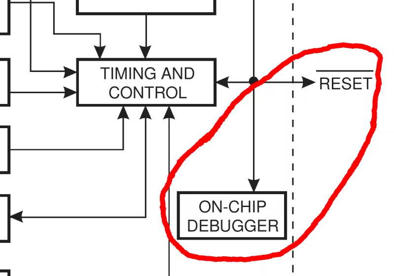
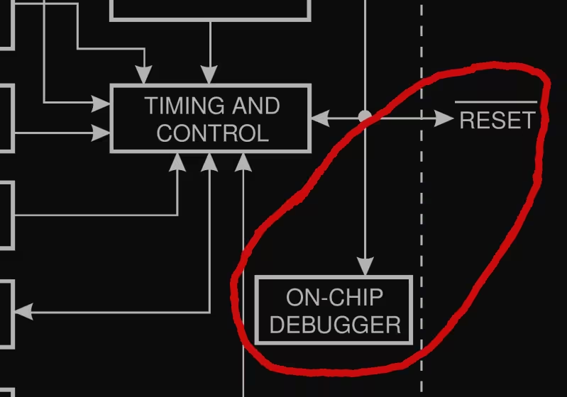
Electrically it's a single wire open drain bi-directional bus, with a pull-up resistor in the AVR. The /reset pin of the AVR is used for all communication. This is quite a neat trick since this pin is directly accessible in most designs. You can program a fuse to configure the pin as either debugwire and reset. On top of this hardware layer sits a transport layer, and on top of that sit the actual debugwire commands. The hardware layer is documented in all kinds of datasheets by Atmel, but the other layers are not.
This is a project that I had been thinking about for quite some time, but was hesitant to start. For me one of the first steps into a new projects usually involves the enthusiastic buying of expensive things. Risk is that once everything is ordered in a rush, I realise that I ordered too many, too few or the wrong parts. Or that while waiting for the parts to arrive I start thinking of my next project. Then when the parts finally arrive, I have already moved on. In this case the expensive part in is an Atmel programmer that supports debugwire. So far I've only ever used cheap open source programmers, so the price of the Atmel programmers came as a bit of a shock. The cheapest one, the AVRDragon, was still nearly €80. With my limited budget I wanted to be sure about this project before investing. I decided to do a proof of concept with the parts at hand first. This would be my first reverse engineering project and I had no idea how hard this would be or what exactly to expect. This would be interesting.
To observe communications between programmer and target you need to know the bus level (logic low or high), bus direction (programmer to target or vice versa) and timing. Since I didn't have a logic analyser, I built one from another AVR with a serial connection to my pc. The analyser is directly connected to the debugwire bus so I could read the level. To get the bus direction I put a series resistor between programmer and target. By measuring the voltage drop over the resistor you could figure out which end pulled the bus low. The resistor should be small enough to not interfere with normal operation, but big enough to get usable readings. The voltage over the resistor is fed to an opamp, used as comparator. The opamp output is connected to the analyser. On every input change the values are sent to the pc. On the pc runs a simple program that records value and timestamp.
Since I didn't have a debugwire capable programmer yet, I used a function generator to generate some pulses and test the analyser. Reading bus level worked fine, but reading bus direction didn't. I only seemed to get random readings. In hindsight, I don't think the comparator had any hysteresis, so it must have been triggering on noise. Or maybe the resistor was too small, or my analyser code was buggy.
I can't recall the exact thought process, but I ended up with an excuse to go and order the expensive programmer.
When the programmer came in I first wanted to see if I could actually use debugwire. I hooked up one of the many ATtiny2313s from my desk and tried to program it. Typically I use avrdude for this and luckily it turned out avrdude supports debugwire. However, in the specific version I was running this feature turned out to be broken. A build from svn did work, so now I could put an AVR into debug mode and back.
Around this time I happened to come across a used HP 16500A Logic Analysis System from 1987. It came with HP 16510B: 35 MHz State / 100 MHz timing module with 40 inputs, built-in floppy drive, touch screen CRT and mouse. Having a bit of a soft spot for old HP measurement gear, I immediately bought it. I had never used a logic analyser before, but I usually learn while doing, so this would be my first steps for using a logic analyser as well.
With the logic analyser hooked up, I could see many of pulses on the bus. Some long, some short, sometimes in long trains and sometimes with long waits in between. But which are the programmer talking to the target and which are the response? This is exactly why I wanted to measure bus direction. Knowing bus level alone is not enough.
As an alternative approach, I figured that I could have a poke around the programmer pcb. There were several big chips on the programmer, maybe I could find interesting signals running between them. If I could find a read / write line, or only one part of the signal without the other, that would make analysing the bus a lot easier.
After lots of poking around on the programmer pcb I had to conclude that there were no interesting signals whatsoever. Maybe it was optimistic to assume that those signals were present. Furthermore, after using the logic analyser for a bit, I realized it was a lot better suited to analysing parallel data streams than serial ones. So back to the drawing board.
After selling the HP logic analyser again, I purchased an Open Logic Sniffer instead. It turned out to be a lot cheaper, more compact and generally more suited to what I was doing than the HP logic analyser was. Being a USB device it could also make full use of the computer screen and facilities.
Luckily I had another idea to detect bus direction, a man in the middle. This would consist of yet another AVR, sitting between programmer and target. There was no more direct connection between programmer and target, the only way to communicate was via the MITM device. When one end pulled the bus low, it is copied over to the other side of the bus, but also to an output for the logic analyser. Now I finally had a way to measure bus direction in addition to bus level. By outputting to the logic analyser, instead of the serial connection I used before, I could make full use of the fancy analysing software that came with it.
With the hardware side of things working, it's time to move on to the transport layer. I saw many pulse trains going back and forth. It was now obvious which pulses were request and which response. But I had no idea how to decode these. Was the pulse time important, or the wait time? Or the number of pulses? It seems I was stuck again.
Then I received an email from my friend Paul Honig (also known as Ranzbak), who knew I was working on debugwire. He had found an article detailing the reversion of the debugwire protocol. It turned out a hacker named Rikus Wessel (RikusW) had succeeded where I was stuck:
I obtained many dumps of the protocol to try to decipher it, turns out it was easier than expected.
Ouch, there went my ego. However, the important thing was somebody had managed to figure out how debugwire works. When I read the article, it made a lot of sense. The transport was standard serial. Why hadn't I thought of that?
RikusW's reverse engineering was even mentioned in the Wikipedia page about debugwire. While reading the Wikipedia article I thought there was something familiar. It took me a moment, but then I realized the article was mostly written by me a year earlier, while waiting for the programmer to arrive, and had forgotten all about it. I felt rather foolish for not checking back on the Wikipedia article during the project, thinking I was the only one working on reversing debugwire.
But since the protocol was now documented, and given my frustration with the project, I considered the case closed and moved on to the next project.
Some years later I was writing this article, documenting my failed attempt to reverse debugwire. While writing I realized that I had never tipped Hackaday about the reversing of debugwire by RikusW. So I sent them an email, referring to RikusW's article, and including a bit about my own failed attempt.
When Hackaday published their article on debugwire, it turned out they not only covered the reversing by RikusW, but included my story as well!
The Hackaday comments showed another surprise. A hacker named David C. W. Brown (dcwbrown) has made an open source programmer that supports debugwire. He built it based on RikusW's work. This is open source at its best.
All the goals from the beginning of the project have been met. Debugwire is now reversed, documented, re-implemented and freely shared with the world. Only I had hoped to contribute a bit more than I did. Nothing in this project has gone according to plan, but I have learned a many new things.
Thanks to RikusW and dcwbrown for their work!