Led tail light
Project | Article by Maarten Tromp | Published , updated | 4653 words
Introduction
There are several advantages of having led lights on your motorcycle, however, mine still used bulbs. So I set about converting the rear light assembly to led.
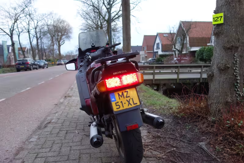 The led rear light assembly installed on my motorcycle
This article featured on Hackaday.
In this article:
As a motorcyclist I want to be safe. Among other things, this means being visible. A good start is to have proper lights on your bike. And for this leds are superior to bulbs. Leds illuminate about 200 ms faster than incandescent bulbs and this demonstratively reduces the number and severity of rear-end collisions. Furthermore, in my experience leds are usually better visible than bulbs.
On my previous motorcycle, a 1999 BMW R1100RT, I had an after market led rear light assembly installed. That assembly, although a bit pricey, was a huge improvement over stock in terms of brightness, visibility and response time.
So when I bought my current motorcycle, a 1999 Honda ST1100 Pan European, I went searching for an after market led rear light assembly again. Unfortunately no such thing existed. I read about people replacing the incandescent bulbs with led bulbs, but that was about it. If I wanted a proper rear light assembly with leds I would have to to remove the stock rear light assembly and mount a generic led one in its place, preferably without looking too bad.
But there is another alternative; make one yourself. My plan is to upgrade the stock rear light assembly to all led. It might not be quite legal to use lights without type approval, but I'm confident I can produce something that is better and safer than stock.
The requirements for this led rear light assembly are mostly common sense. You don't want to end up with something that is in any way inferior to stock.
The led light should be as least as well visible as stock, preferably a lot better. This means brightness, opening angle, surface area and tail light to brake light brightness ratio.
The entire conversion should be mechanically sound. It should be able to handle the moisture, vibrations, mechanical shocks, temperature variations, etc, typical on a motorcycle.
The leds should work on motorcycle battery voltage, that is 10.5 V (flat) to 14.5 V (fast charging).
The stock rear light assembly has 2 identical and independent bulbs for tail light and brake light. If one bulb were to fail, there would still be a working one left. So the led replacement should also have 2 independent circuits as a fail safe. Working as systems administrator on high-available systems, this makes perfect sense to me.
To work on the rear light assembly without having to remove it from my motorcycle, I bought a used one. Now I can work on the led conversion while still having functional lights on my motorcycle. If there ever is a need to go back to stock after the modified lights are installed, I can simply swap the assemblies again.
There are two different versions of the rear light assembly I noticed. There is the US version with separate compartments for left and right tail / brake light, with an unlit space in the middle. And there is the EU version with one big compartment. Since I live in the Netherlands, I worked on the EU version, however I don't think it will be very different on the US version, or any other make or model rear light assembly for that matter.
When the light assembly wouldn't open, I noticed it was sealed shut. There was a waxy substance sealing it. In an attempt to soften the wax I carefully warmed it up with an hot air rework station set to a low temperature. That actually worked, so I used a very small screwdriver and started removing wax where I could reach it. When that was done, I could lift the lens a tiny bit. It took me some more careful heating and prying, but I managed to get the lens completely off eventually. There were some sealant stains on the lens, so I tried rubbing those with isopropanol alcohol and a microfibre cloth. That seemed to do the trick and the lens cleaned up nicely.
Reading up on it later, I found out that people tend to stick their sealed light assemblies in the oven. They're fairly easy to open once warmed up. And if you leave the sealant in place, you can later seal the assembly by heating it up again. This seems an improvement over the method I used.
The base of the light assembly turned out to be curved. I had hoped to lay a PCB flat on the base, but it seemed to be not as easy as that. To come up with PCB shapes that fitted I cut some templates from cardboard.
For this type of application people tend to use flux leds. Those are bright and have a wide opening angle. So that is what I did as well. The rear light assembly has 3 colours; red, orange and white. Led colour should match the lens colour for the best result. White leds behind coloured lenses won't give very good results. Using coloured leds behind a clear lens would work very well, but I don't have one of those.
Leds are obtained from my primary hardware supplier: Ebay. since they're cheap I ordered 100 of both red and orange. That should be plenty. I still have some white leds on stock, so there is no need to order those.
The leds are Luckylight 5mm Piranha Super Flux leds, sold by many different vendors.
There are some really minimalist motorcycle led light designs out there. Some of those you don't even see unless they're switched on. (Such as this one or this one.) Others have patterns or arrows light up or even animate. (Such as this one or this one.) I could do that too, this is my chance to make the world's first space invader tail light. However, the reason I'm working on this rear light assembly is to make it more visible and safe. To me this means having the biggest possible surface area and nothing that distracts from the primary function of showing there's a motorcyclist in front of you.
How many leds should be in this design? The BMW rear light assembly has 50 leds for the tail light, so that will be my starting point.
The best way to evenly fill a surface is a triangular grid. The distance between all leds is constant and that leads to a fairly homogeneous light output. With a bit of puzzling I ended up with a pattern of 4 leds high and 8 wide. So each half of the tail light will have 32 leds, which makes 64 in total.
The aim is to make a simple and robust design. The simplest way to drive a led is with a current-limiting resistor.
Current limiting resistor
Typical forward voltage (VF) for the red red leds is 2.0 V at 20 mA, but according to the datasheet it can vary between leds from 1.6 V to 2.4 V. With a minimum input voltage of 10.5 V, that means we can have a maximum of 4 leds in series. Typical forward voltage over the leds will be 4 * 2.0 V = 8.0 V, the Voltage over the current limiting resistor will be the remainder. At minimum input voltage, Vr = 10.5 V - 8.0 V = 2.5 V, at maximum input voltage Vr = 14.5 V - 8.0 V = 6.5 V. Vr will vary by a factor 2.5 and so will the current through the leds. This will cause a difference in brightness that is bigger than I would like. Let's see if it's any better with less leds in series.
With 2 leds in series (instead of 4) typical forward voltage over the leds will be 2 * 2.0 V = 4.0 V. Minimum Vr = 10.5 V - 4.0 V = 6.5 V, maximum Vr = 14.5 V - 4.0 V = 10.5 V. Vr now varies by a factor of 1.5, and so will current, which is an improvement over 4 leds in series. Brightness variation will probably be acceptable, but now more than half the systems power will be dissipated in the shunt resistor. While it will still consume less power than a bulb, this design lacks elegance.
A linear constant current source is a bit more complex than a resistor, but with varying input voltage you still get a constant current. It's easy to make a simple discrete regulator with a transistor and a few resistors. Easier for me still is to use an integrated regulator such as a LM317 voltage regulator with a shunt resistor. The LM317 will vary its equivalent resistance in the circuit to keep a voltage of exactly 1.25 V over the shunt resistor, and thus have a current of 1.25 V / R through it. Minimum forward voltage over a LM317 is 2 V, so with 4 leds in series the circuit will work down to 10.5 V. Maximum forward voltage over a LM317 is 40 V, but efficiency of the circuit goes down when voltage goes up, just like it did with the current limiting resistor. Maximum current a LM317 can deliver is 1.5 A, but we will stay way below that.
An even more efficient way to dim leds is to use pulse width modulation or a switching power supply. However, it's quite a bit more complex that driving with a constant current. Striving for a simple and robust design I rather go with the current source.
Driving multiple strands of leds
Driving strands of leds in parallel is possible, but you need to take the variance in forward voltage over the leds into account. Worst case one strand is made up of leds with a forward voltage of 1.6 V each, and the next is made up of leds with 2.4 V forward voltage each. For this you need balancing resistors in series with the leds. The value needs to be low enough not to interfere with the current source, but high enough to allow the led strands to balance. With a current of 4 mA per strand (tail light current), and a forward voltage difference of 4 * (2.4 V - 1.6 V) = 3.2 V between strands, you need a resistor of at least V / I = 3.2 V / 4 mA = 800 Ω. However, with 40 mA per strand (brake light current), voltage over that resistor will be I * R = 40 mA * 800 Ω = 32 V, which is a lot more than we have. Luckily in practice the forward voltage differences between leds are a lot smaller, since the datasheet specifies worst case. The small differences will average out once there are a few leds in series. So I chose 10 Ω for the balancing resistors and have no visible brightness difference between leds.
Tail light and brake light wiring
The stock rear light assembly uses BAY15D P21/5W bulbs that have two filaments, one for tail light and one for brake light. Both filaments have a common connection. On this model motorcycle the common is wired to ground. Both tail light and brake light are switched to battery positive. This is something that should be accounted for in the electronics design. Other motorcycles might have the bulbs wired the other way around.
The tail light lamps have another function as well, they also light up the number plate. Since the leds for tail light are red and aimed backwards, they are not of much use producing white light downwards. So we have to add some additional leds for this task.
How should these leds be connected? If they were connected in parallel with the tail light leds, the number plate would also be illuminated brighter when the brake light is active. However, that is also the case with the original bulbs, so I'll just leave that as is.
The turn signal relay is designed to detect faulty lamps and blink faster (hyper-flashing) when it detects one. Since leds draw considerably less power than conventional bulbs, the circuit acts as if a lamp has burned out. Luckily there are a few ways around this.
To trick the turn signal relay into thinking there is a bulb present, you can add a load resistor that would draw the same power a bulb would. A turn signal bulb is 21 W, which is equivalent to a resistance of 6.8 Ω. Power dissipation of the resistor will be 21 W when on, but with 50% duty cycle it will be closer to 10.5 W. The load resistors could be built into turn signal lights, on the led PCB, but that would get quite warm and leds don't respond well to heat. At least we know we can dissipate that much power inside the closure.
Pro: the led rear light assembly will be a drop in replacement for the bulb one. No further motorcycle modifications needed.
Con: there is no energy saving, although this is not one of the requirements. But I find the approach lacks elegance.
Since leds have a much longer lifespan than bulbs, there is not much use of having a faulty lamp detection. Turn signal relays designed for led lights lack the faulty lamp detection and don't have hyper-flashing. They are readily available and inexpensive.
Pro: you don't have to have to deal with resistors and dissipation issues inside a small compartment which is already filled up with a lot of leds.
Con: if you only use leds for the rear turn signals but still have bulbs in the front, you lose your faulty lamp detection for your front turn signal lights.
And there is the hacker approach. You can modify the stock turn signal relay to disable the hyper-flashing function. It is probably not very hard.
Pro: this is the hacker approach. Why buy when you can mod?
Con: if you want to buy a second turn signal relay, so you can have a working one in your motorcycle while you're modifying the second one, you'll probably end up paying more for a used relay than you would for a new led relay.
Since I have not yet replaced the front turn signal bulbs, I want to keep the faulty lamp detection in place. But I don't want to have big, hot resistors in the led turn signals as well. So for now I'll leave the turn signal bulbs in place and only replace the tail light and brake light. When I next have some time and energy to spare I will replace both front and rear turn signals at the same time and modify or replace the turn signal relay.
So this is the resulting schematic diagram. Top half consists of two LM317 current sources. One is for tail light, the other for brake light. A couple of diodes could be added so the tail light, should it be switched off, is also activated when the brake light is, but the brightness difference is negligible, so I left them out for simplicity.
Bottom half is the array of leds with accompanying resistors. The strands of 4 leds are tail light / brake light, the strands of 2 leds are number plate light.
If the tail light / brake light common connection would be wired to positive instead of to ground, the current sources could be moved to the negative side of the led array. To allow for unknown polarity you could include a bridge rectifier, but that would cause an additional voltage drop and heighten the minimum operating voltage by 1.2 V.
Instead of designing a custom PCB I went with prototype board. The design is quite simple and using prototype board will save some time and money. If I were to build more than one, I would go with a proper PCB though.
The prototype boards I had were quite small small, but joining 2 pieces, side by side, was more of less the correct size. On the top and bottom are some copper rods to electrically and mechanically link the boards together. Balancing resistors sit between the leds. Current sources are pop riveted to the centre of the boards.
A properly designed PCB would be an improvement though. It would have more contact surface between board and the light assembly base, which makes for better gluing. There could also be wide copper areas for cooling the LM317 regulators. The shape of the board would be tricky to get right, since there are a lot of curves in the light assembly base.
To do a side by side comparison between bulb and led replacement, I fitted one of each in the rear light assembly. The bulb is powered by an adjustable voltage source (lab power supply), the leds are powered by an adjustable current source (lab power supply in series with electronic load).
It was immediately obvious that the light from the leds differed from the light form the bulb. The red is a slightly deeper shade, while the bulb looks washed out. The led light also seems to come from the entire lens surface instead of just from the centre as it does with the bulb. Led opening angle is also a lot wider wider than the bulb. These are exactly the reasons why I wanted led lights.
To compare light levels I placed a photometer and the light assembly in a cardboard box, to shield it from the surrounding light. The box is open in the photo, but during the measuring the box obviously was closed. Bulb illuminance was measured, at several different voltages, for tail light, brake light and both on at the same time. Then I adjusted led current to create the same illuminance. The results are in the table below.
Tail light and brake light illuminance and equivalent led current
| Bulb | | Led
|
|---|
| Filament | Voltage (V) | Illuminance (lx) | Current (mA)
|
|---|
| Tail | 10.5 | 7.35 | 10.3
|
| 12.0 | 14.3 | 19.6
|
| 13.8 | 21.0 | 28.6
|
| 14.5 | 26.1 | 32.6
|
| Brake | 10.5 | 93.2 | 113.7
|
| 12.0 | 140 | 174.0
|
| 13.8 | 225 | 320
|
| 14.5 | 270 | 386
|
Tail+
brake | 10.5 | 98.2 | 125.9
|
| 12.0 | 164 | 216.9
|
| 14.5 | 287 | 421
|
A couple of observations, none of which came as a surprise:
- Illuminance of the combination of tail light and brake light filaments is the sum of illuminance of both filaments individually.
- There seems to be a linear correlation between led current and illuminance.
- The ratio between tail light and brake light illuminance is approximately 1:10.
Nominal voltage of a charging battery is 13.8 V, so this will be the voltage most commonly present on the motorcycle. Therefore I picked bulb illuminance at 13.8 V as reference. A bit brighter seems nice for the tail light, or at least it seems like that while I'm testing brightness, indoors on the living room table. But if you want to keep the tail light to brake light ratio (which I do), then the brake light becomes incredibly bright. As far as I can tell there is no limit to lamp brightness in the regulations, but I don't want to blind traffic behind me.
With the brightness decided on, we now know the led currents. These will be approximately 32 mA for tail light and 320 mA for brake light per board. This nicely keeps the 1:10 illuminance ratio. Per led the currents will be 4 mA and 40 mA respectively. Driving the leds with 40 mA might or might not be in spec, it's hard to tell as the datasheet is somewhat brief. In any case the brake lights won't be on much of the time.
Updated to add: Maximum current seems to be 20 mA, so driving the leds with 40 mA is definitely out of spec. I will address this in the new version I'm currently working on. In the mean time, if you are copying this design, I would suggest to double the number of leds, use higher power leds or accept limited led lifetime.
Now to calculate the resistor values for the current sources. Let's start with the tail light current. I = 32 mA, V = 1.2 V, R = V / I = 37.5 Ω. Closest E12 resistor is 39 Ω, which is close enough. Now for the brake light current. I = 320 mA, V = 1.2 V, R = V / I = 3.75 Ω. Not really a surprise that with 10 times the current you need 1/10th of the resistance. However, let's calculate power dissipation. Pr = Vr * I = 1.2 V * 320 mA = 0.39 W. This is too much for a 1/4 W resistor. Since I don't have any 1/2 W resistors on stock, I'll have to put two resistors in series or parallel. With 1.2 Ω and 1.8 Ω in series you get quite close to the needed value. Power dissipation is spread more of less equally over both resistors, so that dissipation issue is solved. Now for the power dissipation in the LM317. Pvreg = Vvreg * I = (14.5 V - 8.0 V - 1.2 V) * 320 mA = 1.7 W. That is quite a lot. Not too much for a LM317 to handle, but it will need a heatsink.
Number plate light brightness
With the tail and brake lights sorted, I should take the same steps for the number plate lights. To take illuminance measurements I placed the light assembly back in the box again and put the photometer where the centre of the number plate would be. To stop the light coming out the back of the assembly from interfering with light meant for the number plate I covered up the red part of the lens with a towel. Measurements are done with only 2 out of 4 white leds connected.
Number plate light illuminance and equivalent led current
| Bulb | | Led
|
|---|
| Filament | Voltage (V) | Illuminance (lx) | Current (mA)
|
|---|
| Tail | 13.8 | 33.7 | 54.6
|
The needed current of more than 50 mA is way too much for such small leds. The opening angle on the 5mm white leds is a lot smaller than on the flux leds, and the leds were pointed downwards so most of the light was missing the sensor. After bending the leds downwards a little, so the brightest spot was level with the centre of the number plate, a current of 12.2 mA was enough to match bulb illuminance. That current is more along the lines I expected. Still, the bright spot was just next to the sensor. When I moved the sensor into the focus point of one of the leds, a current of 1.8 mA was enough. That is quite a difference from the starting point. I decided to use the value of 2 mA for the design.
Because the forward voltage for and the current through the white leds will be different from the red leds, we can't just use the same balancing resistors. For tail light I measured 7.69 V over the red led strands (including balancing resistors) and for brake light I measured 10.24 V. Forward voltage over 2 white leds in series is 6.2 V at 2 mA. What would happen if I used a simple current limiting resistor? For tail light Vr = 7.69 V - 6.2 V = 1.5 V, for brake light Vr = 10.24 V - 6.2 V = 4 V. Voltage differs by a factor of 2.5, so will current and so will brightness. While the red leds have a 1:10 ratio in brightness for tail light and brake light, the number plate will only have a 1:2.5 ratio. This is perfectly acceptable to me. Resistor value would be R = V / I = 1.5 V * 2 mA = 750 Ω. Closest lower E12 resistor is 680 Ω.
How much power do these led lights use? The stock tail light uses 2 * 5 W = 10 W. The led replacement uses 2 * 32 mA, P = V * I = 13.8 V * 2 * 32 mA = 0.88 W. The stock brake light uses 2 * 21 W = 42 W. Led replacement uses 8.8 W.
The light assembly, once sealed, should be watertight. So instead of removing the bulb sockets and splicing the led wires directly onto the motorcycle wires, I kept the bulb sockets and seals in place. To electrically connect the boards, I soldered wires directly onto the socket contacts. This worked well, but heating up the massive ground contact took a while.
When I first glued the circuit board onto the light assembly base, the glue stuck very well to the silver paint. Unfortunately the paint didn't stick nearly as good to the black plastic base itself, so everything came out again at a slight pull.
On second try, after sanding the paint from the glue surfaces, the boards stuck to the base very well. The result is somewhat blob-ish, but doesn't come apart easily. I used Bison kit since the bonds stay somewhat flexible which is a good idea with the vibrations on a motorcycle.
The light assembly wouldn't close all the way because of the remaining sealant on the base. Having read about the oven trick I decided to heat up the light assembly and see if I could get it to close again. So I preheated the oven to 75 °C (170 °F) and stuck the assembly in for 10 minutes. Afterwards it was possible to close the assembly by pressing it firmly shut.
Because I removed part of the original sealant I decided to seal the entire assembly with silicone sealant. The result is not unlike the assembly was before I started.
Removing the stock rear light assembly and mounting the modified one was quite simple. You take off the saddle, remove the tool tray and get access to the back (actually the front) of the rear light assembly. All wires are connected with a single connector which is easy to disconnect. The rear light assembly is held in place by 4 screws, and you don't have to remove any fairing. Once the screws are out, you can take the stock assembly out and put the modified one in.
With the modified assembly installed on my motorcycle, it's time to do some real-world testing.
The modified rear light assembly survived its first ride. It was below freezing and there were many speed bumps on the way, but the converted assembly performed flawlessly. Some longer rides are coming up, so plenty of opportunity to review the build some more.
The led unit is nicely visible in daylight. With the stock unit you could hardly tell if the tail light was on during the day, but at least now it clearly lights up. The brake light seems bigger than it was before. A lot more area seems to light up. The faster response time is also noticeable and that was one of the main reasons for doing this conversion. The modified tail light is not much brighter than the stock one, but that was to be expected.
In the dark the led tail light is very well visible. The red is bright, but not too bright. Number plate lighting is acceptable, but I'm not sure it's better than stock. I might try some flux leds instead of the current ones.
This led tail light design and article are released into the public domain. You can find all relevant files in the downloads directory of this article.
Although this build may seem trivial, how much work can it be to hook up a few leds, it took me nearly two weeks to get it done. This is mostly because I wanted it done properly. My safety in traffic depends on it.
During the project I decided to limit the scope by not doing the turn signal light and not designing a PCB. This helped me focus on the main task and I'm not sure my energy and focus would have stretched any longer.
In hindsight I might have gone for a little more brightness. Average car and motorcycle lamp brightness have gone up over the years and this would have been a nice opportunity to bring the rear light assembly light output into this century. If I were to pick a brightness now I would probably have gone with the illuminance values for 14.4 V, which are about 25% higher than the values used in the current build.
But I like what I've built. I'm confident of the quality and hope to enjoy this build for a long time.
Update: 1 year later
Published
One year and a few thousend kilometers later the unit still works well. All the vibration, speed bumps, voltage, temperature and humidity fluctuations do not seem to have negatively impacted the build. There is no sign of degradation of the leds.