DIY automatic transfer switch
Project | Article by Maarten Tromp | Published , updated | 2342 words
Introduction
My friend Herman was looking for an automated transfer switch (ATS), so his PC and modem don't lose power when the circuit breaker trips. An automatic transfer switch will immediately connect your devices to a different power circuit when this happens. Instead of buying a cheap one of questionable quality or spending a lot of money on a professional unit, let's see what we can DIY.
I have also built a DIY uninterruptible power supply (UPS).
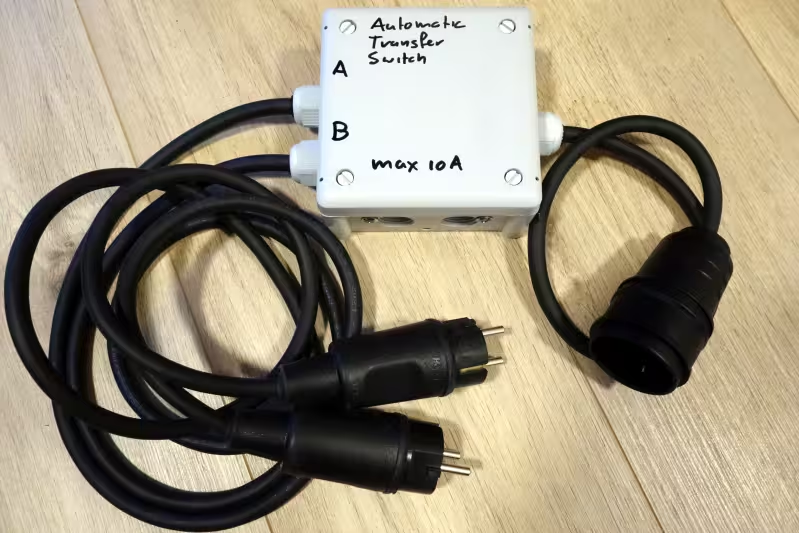 Self made automatic transfer switch
This article featured on Hackaday.
In this article:
What an automatic transfer switch does is quite simple. When power to the primary power input fails, it switches the load over to the backup power input.
Since both power inputs might be connected to entirely different electrical systems or mains phases, you need galvanic isolation between both input circuits. It is important to disconnect one power input before connecting the other. This also makes it impossible to back-feed the interrupted power circuit, which is never a good idea.
This ATS will be used for a couple of computers and connected devices, so it should be able to handle a current of at least a couple of amps.
As last but not least the KISS principle. The simpler the better, complexity is the enemy of security.
There are also many things this ATS will not be, such as power distribution unit (PDU), power filter, power monitoring device or generator switch. Those features will be left to professional models (for now).
The electronics are as minimal as it gets. The entire automatic transfer switch consists of a single electronic part; a relay. Choosing the right relay is not trivial though.
The relay needs to switch mains voltage and a couple of amps, preferably with a bit of headroom. In this case that's 230 V, 50 Hz and around 5 A. The relay itself will be powered by the same voltage.
To get full galvanic isolation between both input circuits you need to switch both live (L) and neutral (N) wires, so the relay should be a 2 pole changeover (CO), also known as double pole double throw (DPDT) type. The mains ground connections should be connected at all times.
Most power relays have considerably higher current handling on the normally open (NO) contacts than on the normally closed (NC) ones, sometimes up to an order of magnitude. For an automatic transfer switch you obviously need both NO and NC contacts to handle the needed high(ish) current.
While you could use 2 separate relays that can handle high-enough current on the NO contacts and combine those into a single CO relay, this soon becomes tricky. First you need to activate the backup power relay when primary power is lost. So you would need a third relay to detect this and operate the backup power relay with backup power, but now you have 3 relays to deal with. And second, you need to make sure that both power relays are under no circumstance activated at the same time. Relays typically have faster operate time than release time, and now you have to get timings right across multiple relays. You might need to use some form of delay to make it all work properly, adding even more complexity. Failing to do this correctly will lead to either back-feeding the interrupted input circuit or tripping residual current devices (RCD) upstream and certainly leave all your critical devices without power.
The only relay I could find that does all this, is available and affordable is the Finder 66.82.8.230.0000. It can switch 250 V, 30 A (NO) / 10 A (NC), operates at 230 V, and costs €10 – €20.
Determining maximum power is a bit tricky, but much the relevant information can be found in the relay datasheet. (The relay used in the ATS is the one on the right-hand side.) The key values to look for are rated load (AC1 and AC15), and motor rating.
The first value is for purely resistive loads, such as incandescent lamps and heaters. This rating is 2500 W.
The next value is for purely inductive loads. This rating is 1200 W. This is considerably lower than the rating for resistive loads, since it takes a lot more current to drive an inductive load. In practice most devices fall somewhere between purely resistive and purely inductive, often leaning towards the resistive side.
Take motors, for example, and for this is the third value. The motor rating is 1500 W.
The safest approach is to use the lowest of the three ratings, which is 1200 W. In real-world scenarios, a load of up to 2000 W would likely be manageable. Though this load would be quite high for a small UPS. If you have a need to handle even higher loads, let me know and I'll provide part numbers for higher capacity industrial-grade parts.
As several Hackaday commenters pointed out, the ATS lacked a switch-back delay. A switch-back delay is a safety feature that allows utility power some time to stabilize before switching back from backup power. This delay prevents the ATS from rapidly switching between primary power and backup during periods of fluctuating mains. A typical delay time is around 30 to 60 seconds.
The simplest way to implement this is by using a "power on delay", or "delay on make timer" device. I opted for an Omron H3Y-2 60 second timer. This delay is powered by mains, so the timer starts when mains comes back on. After the predetermined delay it energizes the relay that switches ATS output from backup to primary input. Most mains delay timers can be used for this purpose.
The addition of the delay timer works perfectly; however, it does not fit within the original enclosure.
The automatic transfer switch should not become the weakest link in the (power) chain, so I prefer a robust mechanical design as well.
Using C13 / C14 sockets ("computer power socket"), or C19 / C20 sockets would be nice and would make the switch more compact. A lot of professional equipment use these sockets too, but in my experience plugs sometimes drop out of these sockets all too easily. Blue CEE 2P+E sockets are more robust and secure, but take up a lot of space and seem overkill for a home situation. Schuco sockets are also quite big and only come in female. My personal favourite is Neutrik Powercon, which is commonly used in professional audio, but is quite unknown in IT. So the best I could come up with is normal schuko male and female plugs.
The plugs are Kopp outdoor models. They're splash-proof and mostly dustproof (IP44) and quite sturdy. The plugs can handle 16 A. I removed the splash cap and child-proof socket shutters from the female plug, so it's easier to use. It will always be plugged in anyway.
Power cabling is made from neoprene rubber. This is tough material and water and heat resistant. With 3x1.5 mm² (16 AWG) it can also handle 16 A.
The enclosure is a Kopp waterproof and dustproof (IP66) outdoor junction box. It is made from tough polypropylene (PP) plastic and comes with 3 good quality fittings.
Wiring to the relay is done with isolated Faston 250 crimp connectors.
All mains earth wires are kept longer than the other wiring, so if somehow a cable is pulled out of the fitting, the earth wire is last to disconnect. All earth wires are connected with a splicing connector.
Mounting the relay in the enclosure turned out to be harder than I had expected. While PP is a nice material for an enclosure, it's not easy to glue. Since I didn't have proper solvents or primer at hand, I considered friction welding, but ended up using mechanical fastening (i.e. nuts and bolts).
Testing the ATS is straight forward. After measuring conductivity to make sure everything is wired up correctly it's time to power it up. I used a few lamps as load and started plugging and unplugging both inputs of the ATS. Except for a slight click of the relay you don't notice it switching over at all. There is not as much as a flicker on any of the lights. According to the datasheet the relay takes 8 ms to operate and 15 ms to release, but since my oscilloscope is currently in storage I can't confirm this. All I can say is the unit seems fast enough to switch my PC over without noticing.
This design, minimal though it is, is released into the public domain as open source hardware. Datasheets can be found in the downloads directory of this article.
So how does this automatic transfer switch compare to the cheap one and the professional one mentioned earlier?
The cheap no-name switch and the self-built one both cost around €50. The self-made one can handle 10 A while the no-name one can handle an order of magnitude more. However, the self-made one is made from good quality brand-name parts and well constructed, while I cannot vouch for the no-name one. Sometimes many corners are cut in order to keep the price as low as possible, not meeting specifications and compromising safety. I'd rather not have one of those devices connected to mains anywhere near me or any of my equipment. But YMMV, the no-name switch might work just fine for your application.
Compared to the professional switch the self-made one only wins on price. Both can handle 10 A, but the professional one has all the bells and whistles and safeties you'd expect in a professional environment. It is most likely better designed and built than the self-made one, and that's why it comes with a professional price tag.
However, for this specific application the self-built automatic transfer switch works just fine. It gets the job done with a minimum of fuss, at an affordable price point. Now that it's finished, I packed it up and shipped it as a gift to Herman, where I'm sure it will be put to good use. Next I'll be building one for myself as well.
Herman's setup
Published
Today Herman received the automatic transfer switch and is currently playing with testing it.
His setup is as follows. If wall power fails, the inline UPS takes over, but what if the UPS fails? Herman told me he had had more down time caused by UPS failure than by power outages. With the addition of the automatic transfer switch, the UPS will be bypassed and the load will be transferred to direct wall power in case the UPS cuts out. Thus creating a redundant power setup on a single circuit with a single UPS.
Stephen's build
Project by Stephen Paine
A few weeks after I published the article, Stephen Paine contacted me, expressing his interest in building his own ATS. A couple of days later he let me know he had completed the project and sent a couple of photos. Most of the parts came from his parts bin; only the relay had to be ordered. Additionally, to differentiate between the power inputs, he used plugs of different colours. For the lid of the box, he repurposed a wall socket, resulting in a compact build. Both power inputs are equipped with LEDs, to monitor their status (not depicted in the photo).
Stephen explained that South Africa is currently experiencing power outages, known as Load Shedding, for a total of 10 hours per day. This translates to three planned outages of either 2 or 4 hours each day or night. He relies on a medical device at night, which requires mains power to function. At home he has a 1.2 kWh battery and inverter to power the device, but travelling presents a challenge. Although he as a portable battery pack and charger, it lacks full UPS functionality and doesn't have enough capacity to sustain the device throughout night. Hence his need for an ATS.
Initially, he bought a good make ATS, but its transfer time was too long, causing the medical device to reboot, interrupting its function. He then acquired another ATS, but it was noisy and only switched in one direction. Not giving up, he decided to try my design and was surprised how well it worked. It switches fast enough that the medical device doesn't notice the changeover, finally solving the issue. Overall it's quite a story but he shared it to underscore his satisfaction with the ATS. Last I heard, he had completed building another ATS, this time for his brother's home-made UPS.
Stephen's account made quite an impression on me. I had designed the ATS to tackle the first-world annoyance of computers losing power, but there are much more significant challenges in the world. I'm pleased to see that this DIY solution can address real-world problems elsewhere.
Marius' build
Project by Marius du Plooy
A few months later, I received the another email about the ATS project. Marius du Plooy had a story similar to Stephen's. Due to the electricity situation in South Africa, he found himself in need of an ATS. Frustrated by the lack of affordable options on the market, he decided to try a DIY solution, and came across my article.
He had done DIY electrical projects before, but this was his first electronics project. To monitor the power inputs, he added status LEDs. He managed to successfully make the ATS in around 1.5 hour and at around 20% less of the cost of a bough out one.
Since its completion, Marius' ATS has been running flawlessly. The change-overs are barely noticeable, and it works well in offloading his UPS. In a follow-up he mentioned he had also built additional units for some close friends.
Marius noticed a growing interest in building these ATSs since they're quite easy to make. Sometimes Power Shedding is used as excuse to overprice essential items, so people turn to DIY. These home-made ATSs would mainly be used in powering essential devices such as fans, lights, routers, TVs, and the occasional fridge. To help everyone understand how much power these units can handle, I've added a chapter below, explaining how to determine this.