Balanced input on subwoofer
Project | Article by Maarten Tromp | Published | 563 words.
Introduction
Always wanted a proper balanced XLR input on a consumer subwoofer? It's not as hard as it might seem, most of it is already in there. Here is the how and why of modifying your subwoofer for balanced input.
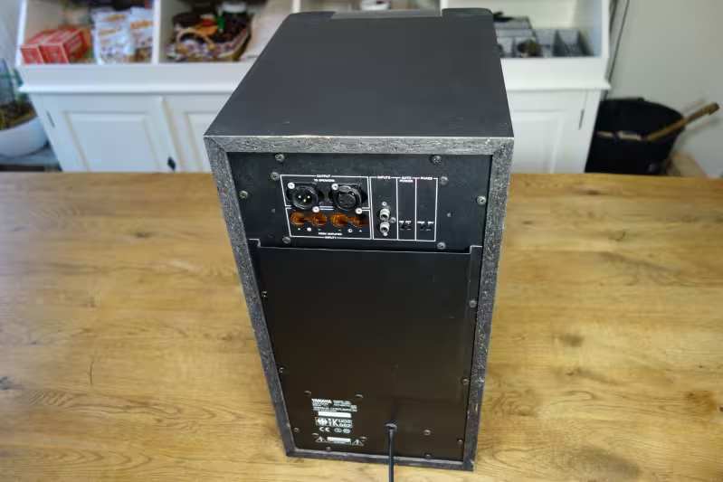 Subwoofer with balanced input added.
In this article:
My studio monitors lack a bit of low end, so I added a pair of subs. The two Yamaha YST-SW80 subwoofers nicely complement the monitors, but the wiring on my desk was a bit hairy. There was a mix of unbalanced audio, speaker cables and mains wiring running back and forth, and there was always quite a bit of hiss and mains hum audible. Recently it has even started to pick up amateur radio transmissions.
To deal with this once and for all I had just finished converting my passive studio monitors to active speakers, with proper balanced inputs. And now it's time to also add some proper balanced inputs to the subwoofers as well.
Looking at the schematics, the subwoofer already had a balanced input on the speaker-level input. The attenuation was too high for balanced line-level signals, but this would only be a minor modification.
Without going into too much detail, signal levels on professional balanced equipment are higher than on consumer unbalanced equipment, but lower than speaker level. A lot has already been written about this, such as this article on Black Ghost Audio.
The new balanced input stage is very similar to the original speaker-level input stage. The series resistors have been lowered from 100 kΩ to 12 kΩ. Two 220 μF electrolytic capacitors have been added to deal with possible DC offset. And a 470 kΩ termination resistor is added. The resulting schematic now also looks quite similar to the unbalanced input stage.
There is no galvanic isolation or protection against phantom power. On proper professional equipment both of these are a must, but for my home studio this is good enough.
The subwoofers turned out to be surprisingly well built. All seams are nicely sealed and there are airtight compartments around all controls and connectors. The PCBs are well labelled and overall a lot of thought seems to have gone into the design.
Since the speaker terminals were no longer needed, those have been removed to make space for the XLR connectors. It was tricky to find a good spot for the new connectors because of all the holes left by the old terminals. Once the position was clear, holes were carefully drilled with a step drill bit.
Then the XLR connectors were pop riveted in place. The new resistors and capacitors were soldered directly onto back of the connectors and wired into the PCB.
It would have been neater to mount the new connectors on a small plate that covers the holes left over from the speaker terminals, but I didn't have any usable material available. Without it the modification looks a bit hacky, but it's mechanically and electrically sound.
Just like the studio monitor modification, it does not sound any different from what I had before. But the mains hum and radio interference have now gone. Without playing audio I can no longer hear weather the subs are powered on or not. Since all changes are on the inside and the back of the subwoofers, the situation on my desk does not look any different from before.
Relevant data sheets can be found in the downloads directory of this article.