Wedding gift for Jeroen and Mingming
project – , author Maarten Tromp, published , last updated , 7442 words.
Today, Saturday 13 July 2019, my friend Jeroen (aka Sprite_tm) is getting married to his fiancée Mingming. Of course I had to make them a gift. It should be geek-compatible, flashy and challenging. So why not build them blinking wedding pictograms? Here is the complete story, complete with all the bumps I hit along the road.
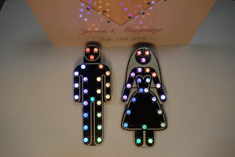 Finished bride and groom PCBs
This article featured on Hackaday and Hackster.io.
In this article:
Jeroen and I met in 2000 during the introduction of Electrical Engineering at the University of Twente. It was immediately obvious that he was a hardware hacker, building cool electronic gadgets with a sort of MacGyver approach. We became friends and both left uni after a couple of years for something more practical.
In 2015 Jeroen told me he had a girlfriend and showed me some photos. Since they live in China, we don't get to meet very often. So far I've seen Mingming once, when they came over between SHA2017 and their flight back to China. I liked meeting her, but I can hardly say I know her.
When Jeroen told me, almost a year ago, that they would be getting married I couldn't help but start thinking about a gift for them. At the time I happened to be working on an article about some of the really cool gifts Jeroen had made for me over the years, so I would like to return the favour. Why buy when you can build something yourself? Now I only had to come up with an idea.
That turned out to be quite a challenge, mostly because of the requirements I had set myself. I want the gift to be visually interesting and appeal to both geeks and non-geeks. It has to be small and light so it could be taken back to China with them. Furthermore, Jeroen is my personal hero when it comes to electronics. He has the ability to come up with cool ideas and then pull them off. It is hard to give him something when I feel he could probably have done a better job himself. And last but not least, I wanted to design and build the gift myself.
However, I managed to come up with something that satisfied all of the requirements.
So the idea is to build them two wearable circuit boards with blinkenlights and wedding-themed artwork. They could even wear it during the party afterwards. This would tick all the boxes; Blinkenlights: check. Interesting for geeks: check. Interesting for non-geeks: check. Light and compact: check. Designed me: check. Built by me: check. Hopelessly complicated design: check. Over engineered: check. Contains slightly explosive battery: check. Challenging: double check.
So I started researching custom PCB shapes and wedding related imagery. While digging I found some gems, such as the particle Christmas tree. It has nice artwork, custom shaped PCB and blinkenlights. Or the Baduino, an Arduino clone by Brainsmoke. These are some nice example of what could be done with PCB.
Then I came across some wedding pictograms. The simplicity of the design immediately appealed to me. It is the standard bathroom pictograms with some minor adjustments that makes it instantly recognisable. This design would also be simple enough to transfer to PCB.
I set the PCB size so that both PCBs would fit inside 100 mm x 100 mm. This was based on the assumption that producing bigger PCBs would be really expensive. Since DirtyPCBs has a relatively cheap 100 mm x 100 mm option, that was what I aimed for. Pictograms of 100 mm high would be big enough to be recognizable and making it bigger would also make it heavier. With white silk screen and black solder resist, it would match the pictogram colours perfectly.
Which parts would I like to use in the design?
Obviously the gift needed lots of lets, but how many exactly, and which ones? 24 Pieces seemed to me the minimum number for some serious blinkiness. It would be enough to roughly outline the shape of the pictogram and I think I could write some interesting demos for this. Any more leds would make it more spectacular, but would also increase current draw. With limited space for a battery and wanting an acceptable runtime, I have to keep the numbers low.
While you could multiplex and drive the leds yourself, I prefer the type of led with built-in driver and controller. You write a RGB value to the led using a serial protocol, and the led will turn that colour. The leds pixels can even be daisy-chained.
Searching the web for such a led, I found the WS2812B. It is a successor to the well known WS2801 and works from a lower voltage. This means the leds can be powered directly from a single LiPo cell. The led has a 5050 form factor (5.0 mm x 5.0 mm) which fits nicely in the design. The leds come in two body colours, white and black, so the led body can even match the background colour of the black PCB and white silk screen.
According to the datasheet the maximum current draw is 20 mA per colour. This makes 24 x 3 x 20 mA = 1.4 A in total. These leds are retina scorching bright, so I doubt they will ever run on full tilt.
Which processor to use for this design? I have used AVRs in several previous projects. Those are perfectly capable to make it all blink. Jeroen got me started with the AVRs, back when we were still in uni, so it would be kind of appropriate to use this processor in a gift for him. But since Jeroen is working for Espressif these days, I also investigated the ESP32. I have seen those processors in several projects, but never developed for one. The hardware is way overkill for just blinking some leds, but it has wifi and bluetooth onboard that could be used for sensing the distance between the two pictograms. Trying to make a hackable gadget, that can be expanded and improved upon, I decided to go with ESP32. It would also be a nice challenge to figure out how to make this work.
Could this processor be powered from a single LiPo cell? The processor needs 3.3 V, so with a ldo 3.3 V regulator it would work. In terms of current the processor needs 0.5 A, with an additional 0.1 A when transmitting. It's a bit on the high side, especially when compared with an AVR, but with the blinkenlights drawing the majority of current, who is gonna notice a bit more current drawn by the processor?
The processor needs to be programmed, firmware debugged and the battery needs to be charged. For this I have added a micro USB connector to the design. It is so much more current than a barrel jack and serial port. Also, everyone has a USB charger these days.
Since the ESP32 has a serial port for programming, we need a USB-to-serial converters. Many solutions exist, but the FT232 is the classic way to go. It supports 3.3 V on the serial side and needs only a single external capacitor. Optionally you could add leds for receive and transmit.
On the web I found another beautiful solution for USB to serial. AVR-CDC exists, an AVR with vUSB to make a USB-to-serial converter. This way there could be both an ESP32 and an AVR in the design. Also, the AVR footprint is smaller and cheaper than the FT232. Unfortunately the suggested ATtiny85 has no hardware UART and the soft UART can't go faster than 4k8 bps, while I would like to reach 115k2 bps. The ATtiny2313 has a hardware UART, but using the correct crystal for USB limits the UART on 38k4 bps. Using a diy solution is of course infinity cooler than an off-the-shelf solution, but it also means additional fiddling and debugging. And right now there are more than enough other challenges in this project, without me adding more. So however beautiful this solution is, I decide to not use it for this project.
To enter ESP32 programming mode you need to reset the device, while holding the boot pin high. A trick called automatic bootloader can be used where the USB-to-serial converter does this for you. The serial handshake lines DTR and RTS are used to control the ESP32 boot and reset pins. Some additional logic is needed to prevent an ESP32 reset when using some serial terminals. This trick is clearly visible in the ESP-WROVER-KIT schematic.
The circuit is designed to run from single LiPo cell. Battery voltage ranges from 3.0 V when empty to 4.2 V when full, with 3.7 V being halfway. The WS2812B works down to 3.5 V, according to the datasheet, and using a low-dropout voltage regulator for the 3.3 V processor voltage, it should also work down to that level.
The battery is always a compromise. More capacity means longer runtime, but also makes the design bigger and heavier (and more expensive). In the current PCB design the maximum continuous space for a battery is 30 mm x 35 mm. After a bit of searching on Ebay I found battery model 602535, which seems to be a standard. It has dimensions of 25 mm x 35 mm x 6 mm and a capacity of around 500 mAh. Versions with and without protection circuitry exist. The biggest capacity I could find on Ebay is 600 mAh, without any protection. Instead I decided to go for 500 mAh batteries with protection circuit.
What would the system runtime be with one of those batteries. With processor and leds, all on full tilt, the current draw is 2 A. With a 500 mAh battery that's 15 minutes runtime. With limited brightness for the leds and the processor being mostly idle I hope for 30 – 60 minutes runtime. Additionally, with a quarter of an hour of runtime, you are discharging at 4 C. Not every battery can handle this kind of current.
To keep an eye on battery voltage, I added battery voltage measurement to the design. In the firmware, I could use all available leds to display a huge battery charge bargraph.
The battery also needs to be charged in circuit. I have never designed a LiPo battery charger before, or even looked into charging that type of battery. What I remember is that LiPo batteries are sensitive to being charged correctly, otherwise they explode. This is exactly why I choose a battery with protection circuitry built-in.
Reading up on LiPo charging circuits, TP4056 seems to be the simplest solution and therefore the way to go. It can do 500 mA charge current and works from the 5 V USB voltage. The feeling that I'm on the right track is confirmed by the fact that the same charger is used in many similar designs, including the SHA2017 badge. Leds can be added for charging and idle. If the battery had a temperature sensor, that could be used as well.
It might be useful if the firmware knows the charging status. So why not hook the status led output up to the processor as well?
I usually source my electronics from Ebay. While searching I had made a typo and nearly bought several pieces of TP4065, which is a different LiPo charger circuit, in a different form factor. Luckily I realized this in time and could then search for the correct model number. The TP4056 however, was not available in low quantities. I ended up buying "Lithium battery charger module" boards with the chip and some additional parts soldered on.
The pictograms are intended to be worn as a badge or brooch. So how exactly to you attach it to your clothing? Several different mechanisms exist such as clips, hinged pins, straight pins, strong magnets or a lanyard. Magnets have the advantage that they do not leave holes in your wedding outfit, but they don't work well on thick clothing. As the pictograms are a bit heavier than your average brooch, this is not a practical solution. With a straight pins you need to place a stop on the inside of your clothing, this might also not be ideal. A lanyard looks too much like a trade show or business event. So that leaves the hinged pin as the best I can come up with.
Here is the final version of the schematic diagram. Even though this diagram is presented to you early in the article, I drew it up near the end of the project, once I started working with Kicad. The software forces you to make a schematic before you can make a PCB. I didn't see the use of it at the time, but now I like that I have a schematic in the documentation.
This version of the schematic corresponds with that is actually on the PCB. During the design I have added and removed some features and replaced some parts with others. After all these changes, this is what I eventually ended up with.
I wanted to test some things before starting on the hardware design. Since I'd never worked with an ESP32 before I wanted to dip my toes in before putting a lot of effort into the hardware design only to change processors later. I happened to have a Espressif Wrover kit (gift from Jeroen) and a SHA2017 badge (gift from Anne Jan), both using the ESP32. I connected some led strips from a previous project (bedroom lighting) and got started with the firmware.
Developing for the ESP32 is clearly more complicated than writing for an AVR, which is the only other microcontroller I have worked with. There is not a single language but a multitude of languages and frameworks available. After researching for several nights I decided to start testing MicroPython and plain esp-idf C to see which works best for me and for the project.
MicroPython turned out to be really easy to work with. Coming from writing mostly assembler, the difference could not be bigger. Python is a very clear and elegant language, with a comprehensive manual and many examples available. Once the ESP32 is flashed with the MicroPython binary, you don't even have to flash any code while developing, just upload and run it on the fly. Writing some demo code for the led strip went smoothly so I then wanted to try communicating between the two ESP32 boards. And this is where the trouble started. The ESP32 has both WiFi and bluetooth on board. MicroPython supports wifi, but no bluetooth, at least not on this platform. That's no problem, we can make it work with wifi, right? Scanning for wifi take a couple of seconds, and while this is happening you can't do anything else. Since the ESP32 is dual core, it should be possible to scan for wifi on one core and run other code on the second core, but this is not supported in MicroPython. They do support threads, but this mucks up timing for the leds not to work properly. So now what?
The other framework I wanted to try was ESP-IDF C. It's fast and efficient, giving you full control, but you need to do everything by hand. Instead of 5 lines of Python code to initialize something as complex as wifi, in C you need 5 pages of cryptic handlers, callback functions and enormous case statements. I don't mind coding simple stuff in C, and have done so many times before, but with something as complex as wifi or bluetooth I'm out of my depth. Writing some blinking demos would work in C as well as MicroPython, but distance sensing might be too much work, costing me more energy time than I have available.
Anyway, writing some code for the ESP32 is possible and I decided to use this processor in the design.
I started this project using gEDA PCB. This was what I had used before and I loved its simplicity. However, most of the parts I picked were not in the library. So I had to design shapes for the ESP32, leds, USB connector, push button and slide switch. Once that was done I had hoped to pick up some speed, but while routing the board I got stuck. It's a crowded board and moving traces around was a lot of work. Then I happened to have an email conversation with Jeroen and I brought up the subject of PCB design, carefully avoiding what exactly it was that I was designing. He suggested Kicad and once again he was right. Kicad takes some getting used to, after using gEDA PCB, but it pays off. I find the routing a lot easier to do, especially with the push-and-shove router.
Unfortunately there is no proper import from one programme to the other, so I had to export my gEDA PCB design to png, import it in Kicad as background and trace everything.
You can get PCBs made in almost any shape, if you specify this in your design. So to get the pictogram outline as your PCB outline, I had to get the reference images into gEDA PCB. A bit of searching learned that that gEDA PCB has the ability to display a background image while creating a PCB. This is done with: pcb --bg-image bride.ppm bride.pcb The image has to be ppm format and will be stretched to the height and width of your PCB. You can then trace the background image where needed. It took a bit of fiddling with height and width to get the proportions right and the PCB height just under 100 mm.
Originally I had planned to cut out the slots between arms and body and between the legs. This would make the PCB more true to the pictogram shape, but it left too little space for the processor and battery. So I filled in the slots with the expected background colour. The processor would fit in the legs and the battery in the body.
Once the PCB shape is done, the design is "coloured" with silk screen. One of the tricky things here is to get the right colour to match or contrast the (expected) background. I expect the groom to wear something dark coloured, so the groom PCB should be outlined in white silkscreen so it contrasts. The bride however, will probably wear something light coloured, so the bride PCB should be outlined in black, so no silkscreen there. For the space between the arms and body it's the other way around. That should match the background.
The part of the PCB you see as the pictogram is the black bit, so any outline should be drawn around the pictogram, not within. Also, gEDA PCB uses a white background for drawing the PCB, which will turn out black, and black colour for silk screen, which will turn out white. It took me a while to wrap my head around this and I ended up making screenshots and inverting colours to double-check if everything was the right colour.
I didn't want any silk screen on the PCB other than the lines needed for the pictogram. But all components have silk screen markings by default. So instead of making all custom Kicad shapes without any silk screen, I found an easy work around. After I generated all the Gerber files for PCB production, I deleted all components from the PCB, keeping the outline, and re-generated the silk screen Gerber file.
After the boards were sent off to production I had some time to reflect and realized that the silk screen was unfinished. The white brides dress and white grooms shirt were left black. I could have done another PCB run, but it felt silly to have the exact same PCB remade only with a different paint job. As a quick fix I have filled in the missing bits with permanent marker.
Fitting everything on the PCB was a real squeeze. The boards are not that big and the battery takes up a lot of space, followed by the ESP32 which also has a keep-out zone for the antenna. The remaining space is fragmented, but most parts are interconnected, leading to many traces being routed through the middle section. Each led connects to power and ground, so I designed power and a ground planes, but with so many traces going back and forth between the sections, the planes keep breaking up. And interconnecting all the plane fragments then leads to even more traces. This is most obvious in he middle section ('body') of the groom. The FT232 USB-to-serial converter sits there, with USB connector and decoupling cap, taking up nearly all the width. Over this sits the reset/boot logic, under this the ESP32. Every connection with the processor needs to pass through this section, including both planes.
Once the groom PCB was routed, the bride was a breeze. I could re-use most of the component placing, but had what felt like huge areas of free space for the traces and planes. What had cost me weeks of evenings for the groom, only cost me hours for the bride.
Originally I intended to put more functionality and parts on the PCB than I was able to fit. I had status leds for the serial communication, status leds for the battery charger, measurement of battery voltage, battery temperature, USB voltage and more in the schematic. Running out of board space I had to ditch more and more features until all would fit on the PCB.
Let's start with two false assumptions. My first assumption was that producing PCBs would be expensive. That is why I kept the design very compact. My second assumption was that cheap PCBs would have a really long lead time. Once the deadline was approaching I got nervous that the PCBs would be even more expensive than I already imagined, because of the rush fees.
As it turns out, production was cheap. I started looking around in the Netherlands, but the companies I found start at 120 Euro for 5 copies of each PCB, with a turn-around time of 2 weeks. This was exactly what I was afraid of. Then I looked at companies in China. This was a relief. Cheapest I could find was PCBWay, charging 10 USD for 10 copies, done in 3 to 4 days, and because this is my first design there, I get a 5 USD discount. This makes PCBWay an order of magnitude cheaper than anything I could find in the Netherlands. Shipping from China per express mail would cost an additional 26 USD and 3 to 4 days, which makes it twice the speed at 1/5 of the cost of getting my board fabbed locally.
Within 6 calender days I had a stack of PCBs on my desk. It turned out just the way I had hoped.
For soldering the PCB top I used solder paste and a hot plate. Two of the ICs have centre pads that are hard to reach by any other method. Since I hadn't ordered stencils with the PCBs, I applied the solder paste it by hand, directly from the syringe. The solder paste is the conventional leaded 63-37 kind.
When designing the PCB it looked beautiful with only silk screen for the art work, but now that I had to assemble the board, the lack of silk screen is really annoying. For every orientation and every value I have to fall back to the design in Kicad.
I also realised that some bits of silk screen were missing. The dress should have been solid white, not just the outline. I must accidentally have deleted it when deleting traces. The white shirt of the groom is also missing. I remember thinking I would draw it on later, but later I was so focussed on the routing that I had forgot all about the artwork. I will attempt to draw it on later using white marker.
The hot plate I use is a scientific model. You simply enter the wanted temperature on the keypad and keep an eye on the display showing measured temperature. Since 63/37 solder paste has a melting point of 183 °C (361 °F), I set the hot plate to 200 °C (392 °F). Once the temperature is reached, carefully slide the PCB on the hot plate. After about two minutes the first solder paste starts to melt. Once the last of the solder paste is molten, carefully slide the PCB off the hot plate again. For this I hold a big aluminium heat sink up to the hot plate and slide the PCB onto is with tweezers.
Hot plate soldering is not very hard, but it is hot, especially when it's over 30℃ (86℉) outside and nearly the same temperature inside.
With all the parts in place, the groom middle section that looked crowded in the design, doesn't look so bad on the PCB.
Soldering the USB connector was was problematic. On the groom PCB I applied a bit too much solder paste and all pins become one big blob of solder. There is too little space between the connector and the FT232 for a soldering iron, so I had to desolder the USB connector, using hot air, clean the PCB and connector and try again. On the bride PCB I must have applied too much solder paste again, since all the pins of the USB connector became once more a big blob of solder. Luckily on this board there was enough space to rework this without having to desolder.
There was a little rework needed on the FT232 as well. It has tight pin spacing and I had applied a bit too much solder paste on some parts, so several pins were soldered together. This is not hard to fix, just apply some flux and use solder wick to clean it up. If needed solder some pins again with 0.5 mm solder and a fine tip and once this is done, clean up with isopropanol and an antistatic PCB brush. Don't use a normal toothbrush, isopropanol will dissolve the hairs.
This reworking brings back memories. My first job in professional electronics was reworking and debugging PCBs. All boards that failed the tests were brought to me to be analysed and repaired. For this I had a lot of very nice equipment and parts available. These days I have nowhere near the fancy equipment, although in some areas I'm getting close.
The top of the PCB is soldered by hand. It could be done on a hot plate as well, if it weren't for all the parts on the other side of the PCB. Soldering by hand is not that hard though, there is only leds and the pads are spaced wide apart.
With the PCBs soldered and a basic firmware ready, it's time to test.
The processor booted fine, I could see the boot log over the USB port. This means that many other things are working as well, such as power and USB-to-serial converter. When the firmware was uploaded I could blink a led, and soon after I could blink a lot of leds.
However, there seemed to be an issue with the leds. Some of them were missing a colour. They blinked fine in green and blue, but didn't show any red. Other leds had green failures. Sometimes the colour had never worked at all, sometimes it had worked but failed after a few minutes. Other leds failed to communicate properly or were only sometimes communicating. So I started reworking. I removed faulty leds and replaced them with brand new ones. Sometimes the problem went away, but just as often new problems would pop up. Leds that had worked fine before were suddenly missing a colour or stopped working at all. Maybe I shouldn't have gotten the cheapest leds from Ebay.
After a while I noticed the leds didn't respond well to heat. With all leds blinking, I started desoldering a faulty led with hot air. As soon as I started, the leds around it started failing as well. I was glad I had started to see a pattern here, because after swapping out so many faulty leds and only getting more failed leds instead of less, you start to doubt your own sanity. So I stopped using hot air and switched to reworking with flux and solder wick. New leds were soldered on on using low temperature for as short as possible, with a cool down period between pins and it paid off. None of the new leds were failing. Did all those leds fail because I accidentally cooked them?
Then there was another weird thing with the leds. There were two spots on the board where communication between leds didn't work. All traces were fine and on the scope I saw that signal was present. But no matter how many times I replaced the leds (both sending and receiving side), communication always failed on the same spot. I cut the traces and rewired with some lacquered copper wire, but that made no difference. It took me a while to figure this one out but I did, with less than 48 hours until the deadline. To match background colours, I used both black and white bodied leds on the bride PCB, and now it appeared that white leds refused to be fed from black leds. All other combinations worked fine. Looking on the scope again I noticed the timing is slightly different between versions. Black leds send a 600 ns pulse to encode a 1, while white leds use a 870 ns pulse. According to the datasheet it should be 800 +/- 150 ns, so the black leds are not up to spec. I had taken the leds to be electrically identical with only different body colours, but hey; live and learn. So I repaired the cut traces and replaced all white leds with black ones. Some leds have been replace 5 times at this point, so I'm amazed the circuit board held up with all this abuse.
With all leds now working, I could do some power measurements. A simple rainbow demo with all leds limited to a brightness of 10 (out of 255) only drew 430 mA. That means we can actually get over 1 hour of runtime! Okay, bluetooth was disabled and full-on white leds would draw more power, but at least we're in the 1-hour-ish zone.
Once power was measured, I installed the final part; the battery. It really filled all the remaining space on the groom PCB. Soldering pads for the battery never made it into the design, so I soldered the battery wires over the output capacitor of the battery charger. The battery itself was fixed with double-sided sticky tape. The result is a bit thicker than I imagined, but now is not the moment to go back to the drawing board. Last thing I did was another power measurement, but this time with the battery installed. The charger draws exactly 500 mA from USB, just as I had hoped.
With the hardware finished, I had to focus on firmware again. After all, without the proper firmware even the best hardware just sits there doing nothing.
Anne Jan Brouwer (aka the_JinX) offered to help out here. He suggested the same approach he had successfully used with the SHA2017 badge firmware. You offload all the difficult stuff to C, so you can then write simple code in MicroPython. He thought adding bluetooth in C would be possible, since you don't have to write a generic driver, implementing all possible scenarios, but only implement the one scenario you actually use. This C / MicroPython hybrid sounded sensible. Since the firmware will be closely related to the SHA2017 badge firmware, we might even make it badge compatible and therefore a bit more universal and hackable. Thanks Anne Jan!
A bluetooth connection would be used for two things. The main thing is distance measurement, the other is synchronisation. I wanted the demos to respond to the distance between bride and groom. When the two are far apart, demos should be slow and black and white only. Once bride and groom become closer, the demos should become more fluent and full colour. For this we need to know the proximity from one to the other. This is exactly what bluetooth gets us. As a bonus, once a connection is established the demos on bride and groom could be synchronised so the same demo is playing at the same step.
Bluetooth Low Energy GATT communication between two nodes works as follows. One node is server, the other is client. The server is continuously advertising itself. The client then discovers the server. If the server is suitable, the client can decide to pair with it. Once connected the client starts issuing commands, which the server fulfils. Since Jeroen has a thing with servers, It makes sense to have the groom be the server. This gives us the following situation; The groom is continuously advertising himself. The bride then discovers the groom. If the groom is suitable, the bide can decide to pair with him. Once connected the bride starts issuing commands, which the groom fulfils. Sounds like a recipe for success.
Bluetooth worked when quickly hacked together as proof of concept, using the Arduino EPS32 wrappers with serial communication, scanning and RSSI (Receive Signal Strength Indication) reporting. Getting this working together in MicroPython turned out to be a bit too much. Currently the state of bluetooth support on MicroPython is pretty immature but moving in a nice cross-platform direction. There was some hope in a two year old implementation by MrSurly whom the SHA2017 badge firmware was co-inspired by for a lot of things in the past. Unfortunately it turned out these changes were so far behind both the mainline MicroPython and esp-idf that working that in would result in weeks of work. Trying to hook the Arduino code straight into an existing MicroPython resulted in way too little stack and heap left over to play with.
So, over to plan B; using WiFi instead.
Despite the WiFi problems with the prototype, we decided to give WiFi another try. How hard can it be? Instead of bluetooth server, the groom would be WiFi access point. The bride would scan for it and report proximity in dBm. Once connected the two would exchange some variables and synchronise demos. Once again it quickly worked, in ideal lab circumstances. The problems started with real-life edge-cases, such as disconnects, toilet visits, you name it. It was not that easy either.
So, over to plan C; no communications and no distance sensing.
With the hard deadline looming and only hours left until the wedding, I had no other option but to have the badges go stand-alone. We can always make an improved version of the firmware available as a firmware update.
The firmware running on both pictograms is identical, but the boards are not. The location of the leds differs, so in the demo code you need to know on which board you're running. Since there is no direct way for the processor of finding this out, each board has a config file with board specific settings, explicitly identifying it as bride or groom PCB. I could have used an input pin on the ESP32 or compared the Wifi MAC address to a hard-coded list, but using a config file seemed the easiest way. Related but not identical; how do we know if the board should be server or client? This is set in the same config file. Separating those two (bride / groom and server / client) gives me the flexibility to re-use the hardware and software later for another wedding, without being restricted to a traditional one-bride-one-groom situation. The firmware is flexible enough to pair two brides or two grooms, but is not yet ready for polyamorous relationships.
While I love looking at visual effects, I have no idea how to recreate them or start new ones from scratch. However, I have put some effort into writing a couple of demos for the boards. Once you get started it's fun to do and I started thinking of variations and getting new ideas all the time. All demos are written in MicroPython.
Each demo has 3 variants. A full colour one for when the bride an groom are close, a black and white one for when the bride and groom are far apart, and one halfway. The framework takes care of distance measurement, passes this on to the demos, and adjusts the timing. When far away, the demos run at half speed compared to when they're close. Until the proximity sensing works, you can switch distance by pushing the boot button on the back.
Besides the physical gift of the pictograms, I also wanted to release this article on Jeroen and Mingmings wedding day. No one expects the happy couple to actually read it on that day, but wouldn't it be nice if they looked back after the wedding and notice the article is dated on their wedding day? Even better, wouldn't it be nice to also have it featured on Hackaday on the same day? So several months in advance I sent them an email, detailing what would be happening and asking for their cooperation. Unfortunately they never got back to me. Later I happened to mention this to Anne Jan and he knew exactly who to poke. At EMF Camp he had met Hackadays Jenny List, and they kept in contact since. She was happy to put the article up on Hackaday on the specified date, we could even choose the exact time of day. Thanks Jenny!
It was great seeing Jeroen and Mingming again after so long and they sure know how to party. There were excellent people, dance dance revolution, BBQ food, top notch ice cream and even the weather played nice.
The gifts were a hit! Mingming and Jeroen really appreciated all the work I put in. They put on the pictograms and wore them for the rest of the night. The blinkenlights work as a beacon, they make it surprisingly easy to locate the bride and groom in a group of people. All the children present especially liked the blinking colours.
Mingming mentioned that the gadgets were small enough to be taken back with them to China. I'm glad that she recognized this design goal. Jeroen said that these PCBs were a lot more professional than the gifts he had made for me, so many years ago.
The battery runtime turned out to be way beyond what I had expected. When we left the party, 6 hours later, the pictograms were still happily blinking away. And the led problems I had experienced were quite common, Jeroen told me. When you move a led slightly, with a pad already soldered, the bond wire snaps of inside the module, resulting in all the failures I had seen.
Several people have remarked that I could (or should) make this into a commercial product. If I ever want to produce in volume, Jeroen happens to know a guy in China...
The wedding pictograms in this article are developed using free and open source software and hardware where possible. The PCB design is started in gEDA PCB and then redrawn in Kicad. Firmware is written using vim and then flashed with esptool and ampy. The demos run on MicroPython.
In turn this design and article are released into the public domain. You can find all relevant files in the downloads directory of this article.
There are many things I have learned from designing and building this project. For instance, this was my first time designing a LiPo charger, using an ESP32 and FT232, hotplate soldering and using silk screen this way.
There are a couple of things I would do differently next time though. What comes to mind is the 100 mm height limit. Scaling up 20% or so would make routing so much easier and leave some board space for all the features I had to ditch because I ran out of board space. Also, I would make silk screen that fits under the components. That way you can see which way to position a led, without any silk screen visible once it's soldered on. Silk screen on the PCB bottom would be handy and I would add the open source hardware logo and a link to the accompanying article.
At some point I realised that all parts I ordered, came from China. The PCB is also produced in China and shipped from there. I then assembled everything here in the Netherlands and give it to Jeroen and Mingming. They will then, probably, take it back to China again with them, completing the circle.
There turns out to be a lot of similarity between the pictograms and the SHA2017 badge. Both designs seem to have a lot of (nearly) identical hardware firmware and production choices. The pictograms were never intended as a copy, it's just that we have made a lot of identical design decisions.
As most people around me know, planning is not one of my strengths and this project once again proved their point. Of the 11 months I had for this project, most work was done in the last couple of weeks. In the beginning I spent a couple of hours per week toying with ideas and making sketches, but by the end I spent more time on the project than on my day job. I kept putting in more and more hours to make the deadline, without compromising the design. The last leds were soldered while packing for vacation, the firmware is written while camping out and this article was finished in a hotel room, minutes before the wedding. I have lost a lot of sleep over this design. My wife also started to complain and she was right. So I hereby pledge to improve my time management for the next project.
Update: implementing bluetooth
published
Nearly a year later, the fact that bluetooth wasn't working still bothered me. After the icons were finished and given away, I have regularly checked if there was bluetooth support in MicroPython yet. In I got lucky, MicroPython now has a working bluetooth low energy implementation. So it was time to write a firmware update with the functionality that was missing during release. With a bit of luck I could have this ready for the lucky couple's first wedding anniversary.
Bluetooth is quite complicated and I'm only just beginning to understand it. The bottom layer is GAP which handles connections. It has the roles central, peripheral, advertiser and observer. On top of GAP sits GATT which deals with exchanging attributes over that connection. It has the roles server and client, which are independent from GAP roles. So far so good, but the server has attributes, which are grouped in services. And then there's characteristics. A great help to me in figuring this out were a Silicon Labs BLE Advertizing primer and a free preview of the O'Reilly book Getting Started with Bluetooth Low Energy.
With documentation and some examples in hand I was able to setup GAP. Both icons broadcast their name (which is set in the config file) as bluetooth device. Both icons also continuously scan for other bluetooth devices, looking for their spouse (which is also set in the config). Luckily the bluetooth standard (and the MicroPython implementation) allows for multiple GAP roles at the same time. When their spouse is found, the received signal strength indication (RSSI) is used to determine the proximity. When they're unable to locate their spouse, this counts as far away.
Unfortunately both bluetooth advertising and the use of interrupts screw up the neopixel timing, just like using threads did. And without these we won't have any proximity sensing or bluetooth communication. Despite disabling interrupts around the critical section of code the leds keep stuttering every so often. In the end I decided that this extra blinkiness was a feature. It adds a bit of extra twinkle to the demos. Also it turns out that bluetooth init can take up to 5 seconds. This is "solved" by setting all leds to a lovely pink during boot up, so there is something to look at while the system initializes.
Once again I ran out of energy and time before everything was finished. GAP and distance sensing are working, but GATT and demo synchronization are not. Oh well, at least proximity is now working and I can always make another firmware update. Happy first anniversary Jeroen and Mingming!